基于R7S910002CBG/10-F0127PA025SC-L159E09主控器件的5.5KW伺服控制系统解决方案
 325
325
 拍明
拍明
概述
伺服控制是对位置、速度、电流等闭环控制。交流伺服电机在功率较大的数控设备自动化、智能控制装备中得以广泛应用,业界期望伺服控制系统具有功能强大、控制方式灵活、技术性能好和可靠性高等特点。本方案优选具有高速处理能力的MCU和高速高效的IGBT模块,组成了一套安全可靠,输出电压、电流指标优秀的紧凑型5.5KW级伺服控制系统。
优势
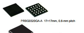
• 32位带浮点运算单元RT/Z1系列MCU R7S910002CBG,集成逆变控制IP和安全加密功能,高采样的速度和精度,使得伺服系统的开关频率达到更高速率,提升了效率,满足业界对电机的转速要求;
【R7S910002CBG】
300 MHz/450 MHz/600 MHz, MCU with ARM Cortex®-R4 and -M3*1, on-chip FPU, 498/747/996DMIPS, up to 1 Mbyte of on-chip extended SRAM, Ethernet MAC, EtherCAT*1, USB 2.0 high-speed,CAN, various communications interfaces such as an SPI multi-I/O bus controller, ΔΣ interface, safety functions, encoder interfaces*1, and security functions*1

Features
■ On-chip 32-bit ARM Cortex-R4 processor
• High-speed realtime control with maximum operating frequency of
300/450/600 MHz
Capable of 498/747/996 DMIPS (in operation at 300/450/600
MHz)
• On-chip 32-bit ARM Cortex-R4 (revision r1p4)
• Tightly coupled memory (TCM) with ECC: 512 Kbytes/32 Kbytes
• Instruction cache/data cache with ECC: 8 Kbytes per cache • High-speed interrupt
• The FPU supports addition, subtraction, multiplication, division,
multiply-and-accumulate, and square-root operations at singleprecision
and double-precision.
• Harvard architecture with 8-stage pipeline
• Supports the memory protection unit (MPU)
• ARM CoreSight architecture, includes support for debugging
through JTAG and SWD interfaces
■ On-chip 32-bit ARM Cortex-M3 processor
(in products incorporating an R-IN engine)
• 150-MHz operating frequency • On-chip 32-bit ARM Cortex-M3 (revision r2p1) • RISC Harvard architecture with 3-stage pipeline • Supports the memory protection unit (MPU)
■ Low power consumption
• Standby mode, sleep mode, and module stop function
■ On-chip extended SRAM
• Up to 1 Mbyte of the on-chip extended SRAM with ECC
• 150 MHz
■ Data transfer
• DMAC: 16 channels × 2 units
• DMAC for the Ethernet controller: 1 channel
■ Event link controller
• Module operations can be started by event signals rather than by
interrupt handlers.
• Linked operation of modules is available even while the CPU is in
the sleep state.
■ Reset and power supply voltage control
• Four reset sources including a pin reset
• Dual power-voltage configuration: 3.3 V (I/O unit), 1.2 V
(internal)
■ Clock functions
• External clock/oscillator input frequency: 25 MHz
• CPU clock frequency: Up to 300/450/600 MHz
• Low-speed on-chip oscillator (LOCO): 240 kHz
■ Independent watchdog timer
• Operated by a clock signal obtained by frequency-dividing the
clock signal from the low-speed on-chip oscillator: Up to 120 kHz
■ Safety functions
• Register write protection, input clock oscillation stop detection,
CRC, IWDTa, and A/D self-diagnosis
• An error control module is incorporated to generate a pin signal
output, interrupt, or internal reset in response to errors originating
in the various modules.
■ Security functions (optional)*2
• Boot mode with security through encryption
■ Encoder interfaces (optional)*3
• EnDat 2.2, BiSS-C, FA-CODER, A-format, and HIPERFACE
DSL-compliant interfaces*4
• Frequency-divided output from an encoder
■ Various communications interfaces • Ethernet
- EtherCAT slave controller: 2 ports (optional) - Ethernet MAC: 1 port (an Ethernet switch is not used)
or
- Ethernet MAC: 1 port (an Ethernet switch to support 2 ports is used) • USB 2.0 high-speed host/function : 1 channel • CAN (compliant with ISO11898-1): 2 channels (max.) • SCIFA with 16-byte transmission and reception FIFOs: 5 channels
• I2C bus interface: 2 channels for transfer at up to 400 kbps
• RSPIa: 4 channels
• SPIBSC: Provides a single interface for multi-I/O compatible
serial flash memory
■ External address space
• Buses for high-speed data transfer at 75 MHz (max.) • Support for up to 6 CS areas • 8-, 16-, or 32-bit bus space is selectable per area
■ Up to 33 extended-function timers
• 16-bit TPUa (12 channels), MTU3a (9 channels), GPTa (4
channels): Input capture, output compare, PWM waveform output
• 16-bit CMT (6 channels), 32-bit CMTW (2 channels)
■ Serial sound interface (1 channel)
■ ΔΣ interface
• Up to 4 ΔΣ modulators are connectable externally.
■ 12-bit A/D converters
• 12 bits × 2 units (max.)
(8 channels for unit 0; 16 channels for unit 1)
• Self diagnosis
• Detection of analog input disconnection
■ Temperature sensor for measuring temperature within the chip
■ General-purpose I/O ports
• 5-V tolerance, open drain, input pull-up
■ Multi-function pin controller
• The locations of input/output functions for peripheral modules are
selectable from among multiple pins.
■ Operating temperature range
• Tj = -40°C to +125°C
Tj: Junction temperature
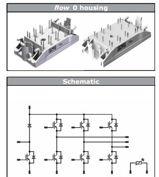
• 7管集成IGBT模块10-F0127PA025SC-L159E09,1200V/25A , 集成温度检测电阻、刹车和三相逆变功能,可以在直流母线做EMC滤波,更方便、更经济。
【10-F0127PA025SC-L159E09】
Features
● Compact Flow 0 housing
● Trench Fieldstop IGBT4 Technology
● Compact and Low Inductance Design
● Built-in NTC
Target applications
● Motor Drives
● Power Generation
Types
● 10-F0127PA025SC-L159E09
● 10-FZ127PA025SC-L159E08

【伺服控制】
伺服控制是为满足某种目的,产生运动和对物体运动进行控制是我们人类最重要的活动之一。伺服控制是对物体运动的位置、速度及加速度等变化量的有效控制。
一般伺服都有三种控制方式: 速度控制方式,转矩控制方式,位置控制方式。
转矩控制
转矩控制方式是通过外部模拟量的输入或直接的地址的赋值来设定电机轴对外的输出转矩的大小,具体表现为例如10V对应5Nm的话,当外部模拟量设定为5V时电机轴输出为2.5Nm:如果电机轴负载低于2.5Nm时电机正转,外部负载等于2.5Nm时电机不转,大于2.5Nm时电机反转(通常在有重力负载情况下产生)。可以通过即时的改变模拟量的设定来改变设定的力矩大小,也可通过通讯方式改变对应的地址的数值来实现。

应用主要在对材质的受力有严格要求的缠绕和放卷的装置中,例如饶线装置或拉光纤设备,转矩的设定要根据缠绕的半径的变化随时更改以确保材质的受力不会随着缠绕半径的变化而改变。
位置控制
位置控制模式一般是通过外部输入的脉冲的频率来确定转动速度的大小,通过脉冲的个数来确定转动的角度,也有些伺服可以通过通讯方式直接对速度和位移进行赋值。由于位置模式可以对速度和位置都有很严格的控制,所以一般应用于定位装置。应用领域如数控机床、印刷机械等等。
速度控制
通过模拟量的输入或脉冲的频率都可以进行转动速度的控制,在有上位控制装置的外环PID控制时速度模式也可以进行定位,但必须把电机的位置信号或直接负载的位置信号给上位反馈以做运算用。位置模式也支持直接负载外环检测位置信号,此时的电机轴端的编码器只检测电机转速,位置信号就由直接的最终负载端的检测装置来提供了,这样的优点在于可以减少中间传动过程中的误差,增加了整个系统的定位精度。
三种对比
如果对电机的速度、位置都没有要求,只要输出一个恒转矩,当然是用转矩模式。
如果对位置和速度有一定的精度要求,而对实时转矩不是很关心,用转矩模式不太方便,用速度或位置模式比较好。如果上位控制器有比较好的闭环控制功能,用速度控制效果会好一点。如果本身要求不是很高,或者,基本没有实时性的要求,用位置控制方式对上位控制器没有很高的要求。
就伺服驱动器的响应速度来看,转矩模式运算量最小,驱动器对控制信号的响应最快;位置模式运算量最大,驱动器对控制信号的响应最慢。
对运动中的动态性能有比较高的要求时,需要实时对电机进行调整。那么如果控制器本身的运算速度很慢(比如PLC,或低端运动控制器),就用位置方式控制。如果控制器运算速度比较快,可以用速度方式,把位置环从驱动器移到控制器上,减少驱动器的工作量,提高效率(比如大部分中高端运动控制器);如果有更好的上位控制器,还可以用转矩方式控制,把速度环也从驱动器上移开,这一般只是高端专用控制器才能这么干,而且,这时完全不需要使用伺服电机。
责任编辑:Davia
【免责声明】
1、本文内容、数据、图表等来源于网络引用或其他公开资料,版权归属原作者、原发表出处。若版权所有方对本文的引用持有异议,请联系拍明芯城(marketing@iczoom.com),本方将及时处理。
2、本文的引用仅供读者交流学习使用,不涉及商业目的。
3、本文内容仅代表作者观点,拍明芯城不对内容的准确性、可靠性或完整性提供明示或暗示的保证。读者阅读本文后做出的决定或行为,是基于自主意愿和独立判断做出的,请读者明确相关结果。
4、如需转载本方拥有版权的文章,请联系拍明芯城(marketing@iczoom.com)注明“转载原因”。未经允许私自转载拍明芯城将保留追究其法律责任的权利。
拍明芯城拥有对此声明的最终解释权。


 产品分类
产品分类


 2012- 2022 拍明芯城ICZOOM.com 版权所有 客服热线:400-693-8369 (9:00-18:00)


