


 产品分类
产品分类
基于Infineon公司的XMC1302马达控制解决方案
 284
284
 拍明
拍明
原标题:Infineon XMC1302马达控制解决方案
infineon公司的XMC1302是基于32位ARM Cortex-M0处理器核的XMC™1000系列中一员,具有超低功耗,8KB ROM,16KB高速SRAM和高达200KB 闪存程序和数据存储器,以及多种通信接口,模拟前端接口和工业控制接口,主要用在马达控制,数字电源转换和LED照明等.本文介绍了XMC1302主要特性,系统框图,以及评估板Eval_M1-1302主要特性和框图,电路图,材料清单和PCB设计图.
The XMC1300 devices are members of the XMC™1000 Family of microcontrollers based
on the ARM Cortex-M0 processor core. The XMC1300 series addresses the real-time
control needs of motor control, digital power conversion. It also features peripherals for
LED Lighting applications.
XMC1302主要特性:
CPU Subsystem
• CPU Core
– High-performance 32-bit ARM Cortex-M0 CPU
– Most 16-bit Thumb and subset of 32-bit Thumb2 instruction set
– Single cycle 32-bit hardware multiplier
– System timer (SysTick) for Operating System support
– Ultra low power consumption
• Nested Vectored Interrupt Controller (NVIC)
• Event Request Unit (ERU) for processing of external and internal service requests
• MATH Co-processor (MATH)
– CORDIC unit for trigonometric calculation
– division unit
On-Chip Memories
• 8 kbytes on-chip ROM
• 16 kbytes on-chip high-speed SRAM
• up to 200 kbytes on-chip Flash program and data memory
Communication Peripherals
• Two Universal Serial Interface Channels (USIC), usable as UART, double-SPI, quad-SPI, IIC, IIS and LIN interfaces
Analog Frontend Peripherals
• A/D Converters
– up to 12 analog input pins
– 2 sample and hold stages with 8 analog input channels each
– fast 12-bit analog to digital converter with adjustable gain
• Up to 8 channels of out of range comparators (ORC)
• Up to 3 fast analog comparators (ACMP)
• Temperature Sensor (TSE)
Industrial Control Peripherals
• Capture/Compare Units 4 (CCU4) as general purpose timers
• Capture/Compare Units 8 (CCU8) for motor control and power conversion
• Position Interfaces (POSIF) for hall and quadrature encoders and motor positioning
• Brightness and Colour Control Unit (BCCU), for LED color and dimming application
System Control
• Window Watchdog Timer (WDT) for safety sensitive applications
• Real Time Clock module with alarm support (RTC)
• System Control Unit (SCU) for system configuration and control
• Pseudo random number generator (PRNG) for fast random data generation
Input/Output Lines
• Tri-stated in input mode
• Push/pull or open drain output mode
Configurable pad hysteresis
On-Chip Debug Support
• Support for debug features: 4 breakpoints, 2 watchpoints
• Various interfaces: ARM serial wire debug (SWD), single pin debug (SPD)
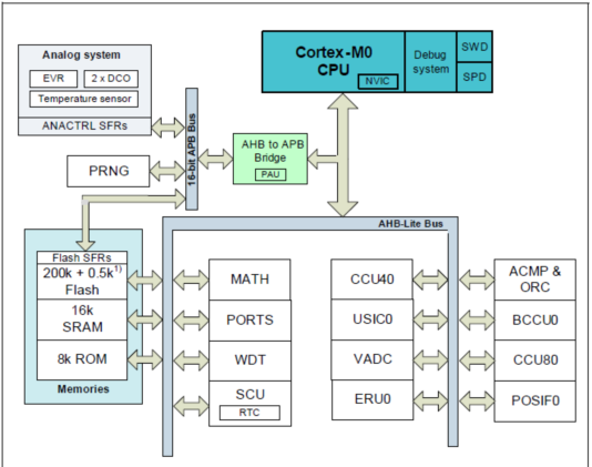
图1. XMC1302系统框图
评估板Eval_M1-1302
The Eval_M1-1302 board houses the XMC1302 Microcontroller from Infineon Technologies, a power board connector, an interface for bipolar latching Hall-effect position sensors, an encoder sensor interface connector, a USIC interface and an isolated on-board debug interface. The board along with a three phase inverter demonstrates the capabilities of the XMC1302 in motor control application. The main use case for this board is to demonstrate the motor control features of the XMC1302. The focus is safe operation under evaluation conditions.
评估板Eval_M1-1302主要特性:
• Infineon XMC1302 Microcontroller which is an ARM® Cortex™-M0-based device with 200 kByte on chip flash memory inside a TSSOP38 package
• Connection to power section via the power board connector
• Combined hall sensor and encoder interface
• USIC interface connector for connection of UART, SPI or I2C
• 6 LEDs
− 2 Power indicating LEDs
− 1 User LED
− 1 Encoder enable LED
− 2 Debug LEDs (DEBUG, COM)
• Isolated Debug options
− SEGGER J-Link LITE on-board debugger via USB connector
− 16-pin debug connector supporting the Infineon DriveMonitor USB Stick V2
• Isolated Connectivity
− UART channel of SEGGER J-Link LITE on-board debugger via USB connector
• Power supply of the MCU domain, providing 3.3 V and 5 V via connector J3
• Power supply of the isolated debug domain
− Via debug USB connector
− Via 16-pin connector which interfaces with the DriveMonitor USB Stick V2
评估板Eval_M1-1302框图包括:
• Power Board connector
• HALL interface connector for position sensing
• Encoder interface connector
• Encoder Enable signals via GPIO
• One user LED connected to GPIO
• USIC0 interface connector
• Isolated on-board debugger via Debug Micro-USB connector with UART
• 16-pin debug connector for the Drive Monitor USB Stick V2
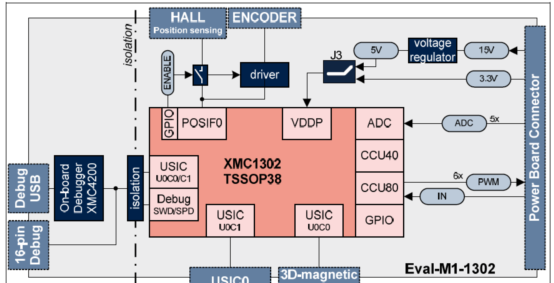
图2. 评估板Eval_M1-1302框图
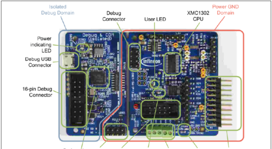
图3. 评估板Eval_M1-1302外形图
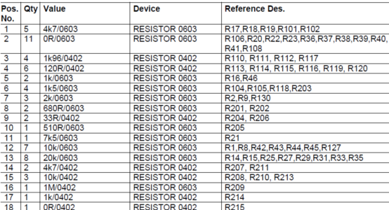
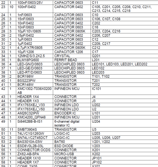
评估板Eval_M1-1302材料清单:
详情请见:
![]() Infineon-xmc1300_AB-DS-v01_07-EN.pdf
Infineon-xmc1300_AB-DS-v01_07-EN.pdf
![]() Infineon-AN2016-22-Eval-M1-1302 Control board-AN-v01_00-EN.pdf
Infineon-AN2016-22-Eval-M1-1302 Control board-AN-v01_00-EN.pdf
责任编辑:HanFeng
【免责声明】
1、本文内容、数据、图表等来源于网络引用或其他公开资料,版权归属原作者、原发表出处。若版权所有方对本文的引用持有异议,请联系拍明芯城(marketing@iczoom.com),本方将及时处理。
2、本文的引用仅供读者交流学习使用,不涉及商业目的。
3、本文内容仅代表作者观点,拍明芯城不对内容的准确性、可靠性或完整性提供明示或暗示的保证。读者阅读本文后做出的决定或行为,是基于自主意愿和独立判断做出的,请读者明确相关结果。
4、如需转载本方拥有版权的文章,请联系拍明芯城(marketing@iczoom.com)注明“转载原因”。未经允许私自转载拍明芯城将保留追究其法律责任的权利。
拍明芯城拥有对此声明的最终解释权。
相关资讯
:
基于MC33771主控芯片的新能源锂电池管理系统解决方案

AMIC110 32位Sitara ARM MCU开发方案

基于AMIC110多协议可编程工业通信处理器的32位Sitara ARM MCU开发方案

基于展讯SC9820超低成本LTE芯片平台的儿童智能手表解决方案

基于TI公司的AM437x双照相机参考设计

基于MTK6580芯片的W2智能手表解决方案


 2012- 2022 拍明芯城ICZOOM.com 版权所有 客服热线:400-693-8369 (9:00-18:00)


