


 产品分类
产品分类
Microchip MCP39F511A AC/DC转换器双模式电源监视方案
 115
115
 拍明
拍明
原标题:Microchip MCP39F511A AC/DC转换器双模式电源监视方案
Microchip公司的MCP39F511A是高度集成完整单相电源监视集成电路,包括两路Delta-Sigma ADC,16位计算引擎,EEPROM 和灵活2线接口,设计用于实时测量AC或DC电源的输入功率,能够检测输入电压以便工作于DC或是AC模式.集成的低漂移基准电压具有7 ppm/℃,SINAD性能达到94.5dB,动态范围4000:1时的精度0.1%,扩展的温度范围-40℃ 到 +125℃,主要用在智能家庭/城市的电源监测,工业照明监测,再生能源的功率测量,智能电源分配单元和服务器电源监视器.本文介绍了MCP39F511A主要特性,功能框图和应用电路以及MCP39F511A电源监视器演示板ADM00667主要特性,电路图,材料清单和PCB设计图.
The MCP39F511A device is a highly-integrated,complete single-phase power-monitoring IC designedfor real-time measurement of input power for AC or DCpower supplies, making it suitable for a wide range ofconsumer and industrial applications. It is capable of detecting the input voltage in order to work as DC or ACmode. It includes dual-channel Delta-Sigma ADCs, a16-bit calculation engine, EEPROM and a flexible2-wire interface. Separate AC and DC calibrationregisters are provided, to ensure high-accuracymeasurements in both modes. An integrated low-driftvoltage reference with 7 ppm/℃ in addition to 94.5 dBof SINAD performance on each measurement channelallows for better than 0.1% accurate designs across a4000:1 dynamic range.
MCP39F511A主要特性:
• Real-Time Measurement of Input Power for AC orDC Supplies
• AC/DC Dual-Mode Power Monitoring AccuracyCapable of 0.1% Error Across 4000:1 DynamicRange
• Automatic Sensing and Switching Between ACand DC Modes
• Built-In Calculations on Fast 16-Bit ProcessingCore
- Active and Reactive Energy Accumulation
- Active, Reactive, Apparent Power
- True RMS Current, RMS Voltage
- Line Frequency, Power Factor
• 64-bit Wide Import and Export Active EnergyAccumulation Registers
• 64-bit Four Quadrant Reactive EnergyAccumulation Registers
• Automatic Saving the Energy AccumulationRegisters into EEPROM at Power Off
• Automatic Loading the Energy AccumulationRegisters from EEPROM at Power On
• Signed Active and Reactive Power Outputs
• Dedicated Zero Crossing Detection (ZCD) PinOutput with Less than 200 μs Latency
• Dedicated PWM Output Pin with ProgrammableFrequency and Duty Cycle
• Automatic Event Pin Control through Fast VoltageSag/Surge Detection
• Two Wire Serial Protocol with Selectable BaudRate Up to 115.2 kbps using Universal Asynchronous Receiver/Transmitter (UART)
• Four Independent Registers for Minimum andMaximum Output Quantity Tracking
• Fast Calibration Routines and SimplifiedCommand Protocol
• 512 Bytes User-Accessible EEPROM throughPage Read/Write Commands
• Low-Drift Internal Voltage Reference, 7 ppm/°CTypical
• 28-lead 5x5 QFN Package
• Extended Temperature Range -40℃ to +125℃
MCP39F511A应用:
• Power Monitoring and Management for SmartHome/City
• Industrial Lighting Power Monitoring
• Power Measurement for Renewable Energy System
• Intelligent Power Distribution Units
• Server Power Monitor

图1.MCP39F511A功能框图

图2. MCP39F511A典型应用电路图-单相两线
MCP39F511A电源监视器演示板ADM00667
The MCP39F511A Power Monitor Demonstration Board is a fully-functional,single-phase power and energy monitor. The system calculates active power, reactivepower, RMS current, RMS voltage, active energy (both import and export), reactiveenergy and other typical power quantities, as defined in the MCP39F511A data sheet.
The MCP39F511A Power Monitor Demonstration Board uses the Power Monitor Utility software for evaluation through a USB connection to the board. The Power MonitorUtility software is used to calibrate and monitor the system, and can be used to createcustom calibration setups. For most accuracy requirements, only a single-pointcalibration is needed. The software offers an automated step-by-step calibrationprocess that can be used to quickly calibrate power meters.
A download link for this software can be found on the demonstration board’s web page.For instructions on how to use the software, refer to the software’s supportingdocumentation included within the application installation package.
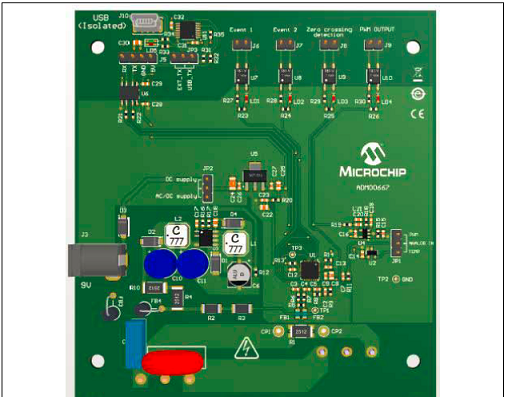
图3.电源监视器演示板ADM00667外形图
This MCP39F511A Power Monitor Demonstration Board kit includes:
• MCP39F511A Power Monitor Demonstration Board (ADM00667)
• AC Line Cable
• IEC to Female AC Load Cable
• Mini-USB Cable
• Important Information Sheet

图4.电源监视器演示板ADM00667顶视图

图6.电源监视器演示板ADM00667电路图(1)

图7.电源监视器演示板ADM00667电路图(2)
电源监视器演示板ADM00667材料清单:


机械部分材料清单(BOM):

责任编辑:HanFeng
【免责声明】
1、本文内容、数据、图表等来源于网络引用或其他公开资料,版权归属原作者、原发表出处。若版权所有方对本文的引用持有异议,请联系拍明芯城(marketing@iczoom.com),本方将及时处理。
2、本文的引用仅供读者交流学习使用,不涉及商业目的。
3、本文内容仅代表作者观点,拍明芯城不对内容的准确性、可靠性或完整性提供明示或暗示的保证。读者阅读本文后做出的决定或行为,是基于自主意愿和独立判断做出的,请读者明确相关结果。
4、如需转载本方拥有版权的文章,请联系拍明芯城(marketing@iczoom.com)注明“转载原因”。未经允许私自转载拍明芯城将保留追究其法律责任的权利。
拍明芯城拥有对此声明的最终解释权。
相关资讯
:
基于MC33771主控芯片的新能源锂电池管理系统解决方案

AMIC110 32位Sitara ARM MCU开发方案

基于AMIC110多协议可编程工业通信处理器的32位Sitara ARM MCU开发方案

基于展讯SC9820超低成本LTE芯片平台的儿童智能手表解决方案

基于TI公司的AM437x双照相机参考设计

基于MTK6580芯片的W2智能手表解决方案


 2012- 2022 拍明芯城ICZOOM.com 版权所有 客服热线:400-693-8369 (9:00-18:00)


