


 产品分类
产品分类
Fairchild FAN302HL低待机功耗PWM电源控制方案
 67
67
 拍明
拍明
原标题:Fairchild FAN302HL低待机功耗PWM电源控制方案
Fairchild公司的FAN302HL是低待机功耗电池充电器用的PWM电源控制器, 采用恒流模式控制,在230VAC时的带机功耗低于10mW,固定PWM频率85kHz和跳频,以降低EMI,工作电流3.5A,栅极输出最大电压箝位在 15V,具有高压起动功能,主要用在手机,无绳电话,PDA和数码相机等电池充电器.本文介绍了FAN302HL主要特性, 功能方框图, 高压(HV)起动电路图, 反激转换器电路图和典型应用电路图以及变压器结构图和绕组指标.
FAN302HL PWM Controller for Low Standby Power Battery-Charger Applications
This highly integrated PWM controller, FAN302HL, provides several features to enhance the performance of general flyback converters. The constant-current control, proprietary topology enables simplified circuit designs without secondary feedback circuitry for batterycharger applications.
A proprietary Burst-Mode function with low operation current minimizes standby power consumption.
The FAN302HL controller also provides several protections. Cycle-by-cycle current limiting ensures the fixed peak current limit level, even if a short circuit occurs. The gate output is clamped at 15V to protect the power MOS from high gate-source voltage conditions. If either VS OVP or internal OTP is triggered, the circuit enters Latch Mode until AC power is removed.
Using FAN302HL, a charger can be implemented with few external components and minimized cost, compared to a conventional design or a linear transformer.
FAN302HL主要特性:
Ultra-Low Standby Power: Under 10mW at 230VAC
Constant-Current (CC) Control without Secondary- Feedback Circuitry
Fixed PWM Frequency at 85kHz with Frequency Hopping to Solve EMI Problem
High-Voltage Startup
Low Operating Current: 3.5mA
Peak-Current-Mode Control in CV Regulation
Cycle-by-Cycle Current Limiting
VDD Over-Voltage Protection (Auto-Restart)
VS Over-Voltage Protection (Latch Mode)
VDD Under-Voltage Lockout (UVLO)
Gate Output Maximum Voltage Clamped at 15V
Fixed Over-Temperature Protection (Latch Mode)
Available in an 8-Lead SOIC Package
FAN302HL应用:
Battery chargers for cellular phones, cordless phones, PDA, digital cameras, and power tools. Replaces linear transformers and RCC SMPS.
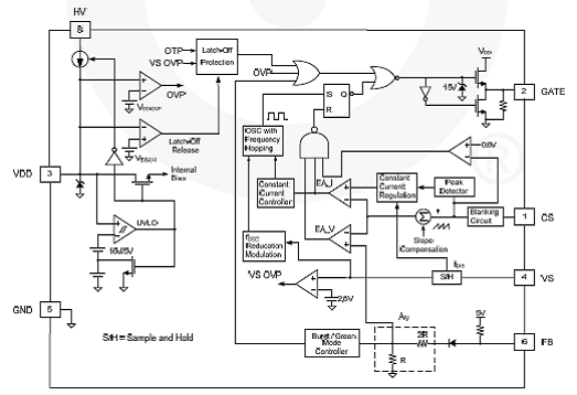
图1.FAN302HL功能方框图
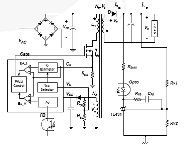
图2.FAN302HL简化反激转换器电路图
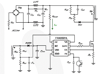
图3.FAN302HL高压(HV)起动电路图
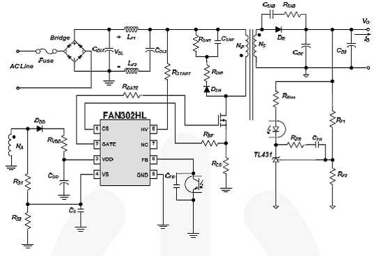
图4.FAN302HL典型应用电路
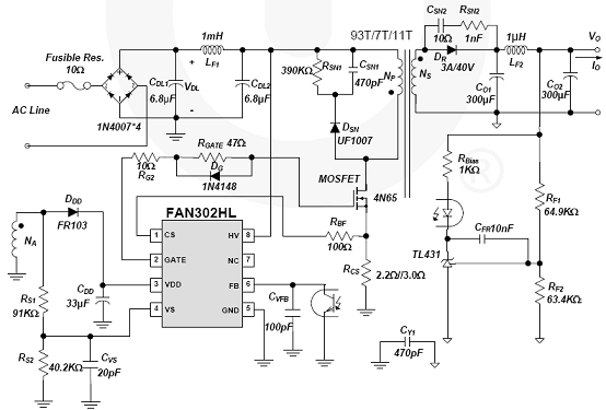
图5.FAN302HL典型应用电路图
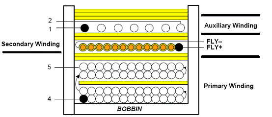
图6.FAN302HL变压器结构图
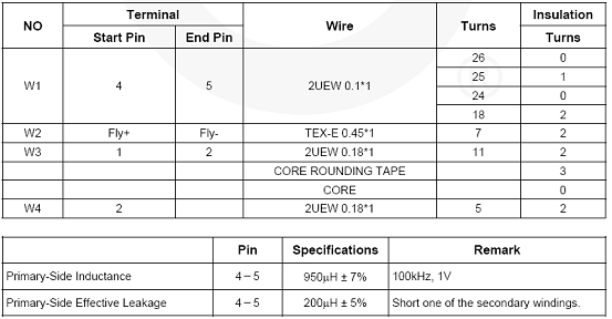
变压器绕组指标:
责任编辑:HanFeng
【免责声明】
1、本文内容、数据、图表等来源于网络引用或其他公开资料,版权归属原作者、原发表出处。若版权所有方对本文的引用持有异议,请联系拍明芯城(marketing@iczoom.com),本方将及时处理。
2、本文的引用仅供读者交流学习使用,不涉及商业目的。
3、本文内容仅代表作者观点,拍明芯城不对内容的准确性、可靠性或完整性提供明示或暗示的保证。读者阅读本文后做出的决定或行为,是基于自主意愿和独立判断做出的,请读者明确相关结果。
4、如需转载本方拥有版权的文章,请联系拍明芯城(marketing@iczoom.com)注明“转载原因”。未经允许私自转载拍明芯城将保留追究其法律责任的权利。
拍明芯城拥有对此声明的最终解释权。
相关资讯
:
基于MC33771主控芯片的新能源锂电池管理系统解决方案

AMIC110 32位Sitara ARM MCU开发方案

基于AMIC110多协议可编程工业通信处理器的32位Sitara ARM MCU开发方案

基于展讯SC9820超低成本LTE芯片平台的儿童智能手表解决方案

基于TI公司的AM437x双照相机参考设计

基于MTK6580芯片的W2智能手表解决方案


 2012- 2022 拍明芯城ICZOOM.com 版权所有 客服热线:400-693-8369 (9:00-18:00)


