


 产品分类
产品分类
基于NXP的MPC5643L 32位MCU开发和三相BLDC/PMSM低压电源参考设计
 273
273
 拍明
拍明
原标题:NXP MPC5643L 32位MCU开发和三相BLDC/PMSM低压电源参考设计
NXP公司的MPC5643L系列是基于32位Power Architecture的系统级芯片(SoC),采用高性能e200z4d双内核,工作频率高达120MHz,具有可变长度编码(VLE),存储器管理单元(MMU),带误差检测代码的4KB指令缓存和信号处理引擎(SPE),其增强特性适合用在嵌入使应用,特别是汽车应用控制器.本文介绍了MPC5643L主要特性,框图,评估板KITMPC5643DBEVM主要特性和硬件开发配置图,以及电路图,材料清单和PCB设计图.此外还介绍了采用MPC5643L MCU三相BLDC/PMSM低压电源参考设计框图和电路图.
The MPC5643L series microcontrollers are system-on-chip devices that are built on Power Architecture technology and containenhancements that improve the architecture’s fit in embedded applications, include additional instruction support for digitalsignal processing (DSP) and integrate technologies such as an enhanced time processor unit, enhanced queued analog-to-digitalconverter, Controller Area Network, and an enhanced modular input-output system.
The MPC5643L family of 32-bit microcontrollers is the latest achievement in integrated automotive application controllers. Itbelongs to an expanding range of automotive-focused products designed to address electrical hydraulic power steering (EHPS),electric power steering (EPS) and airbag applications. The advanced and cost-efficient host processor core of the MPC5643Lautomotive controller family complies with the Power Architecture embedded category. It operates at speeds as high as120 MHz and offers high-performance processing optimized for low power consumption. It capitalizes on the availabledevelopment infrastructure of current Power Architecture devices and is supported with software drivers, operating systems andconfiguration code to assist with users’ implementations.
MPC5643L主要特性:
• High-performance e200z4d dual core
— 32-bit Power Architecture® technology CPU
— Core frequency as high as 120 MHz
— Dual issue five-stage pipeline core
— Variable Length Encoding (VLE)
— Memory Management Unit (MMU)
— 4 KB instruction cache with error detection code
— Signal processing engine (SPE)
• Memory available
— 1 MB flash memory with ECC
— 128 KB on-chip SRAM with ECC
— Built-in RWW capabilities for EEPROM emulation
• SIL3/ASILD innovative safety concept: LockStep mode andFail-safe protection
— Sphere of replication (SoR) for key components (such asCPU core, eDMA, crossbar switch)
— Fault collection and control unit (FCCU)
— Redundancy control and checker unit (RCCU) on outputsof the SoR connected to FCCU
— Boot-time Built-In Self-Test for Memory (MBIST) andLogic (LBIST) triggered by hardware
— Boot-time Built-In Self-Test for ADC and flash memorytriggered by software
— Replicated safety enhanced watchdog
— Replicated junction temperature sensor
— Non-maskableinterrupt (NMI)
— 16-region memory protection unit (MPU)
— Clock monitoring units (CMU)
— Power management unit (PMU)
— Cyclic redundancy check (CRC) unit
• Decoupled Parallel mode for high-performance use ofreplicated cores
• Nexus Class 3+ interface
• Interrupts
— Replicated 16-priority controller
— Replicated 16-channel eDMA controller
• GPIOs individually programmable as input, output orspecial function
• Three 6-channel general-purpose eTimer units
• 2 FlexPWM units
— Four 16-bit channels per module
• Communications interfaces
— 2 LINFlexD channels
— 3 DSPI channels with automatic chip selectgeneration
— 2 FlexCAN interfaces (2.0B Active) with 32message objects
— FlexRay module (V2.1 Rev. A) with 2 channels,64 message buffers and data rates up to 10 Mbit/s
• Two 12-bit analog-to-digital converters (ADCs)
— 16 input channels
— Programmable cross triggering unit (CTU) tosynchronize ADCs conversion with timer andPWM
• Sine wave generator (D/A with low pass filter)
• On-chip CAN/UART bootstrap loader
• Single 3.0 V to 3.6 V voltage supply
• Ambient temperature range –40 ℃ to 125 ℃
• Junction temperature range –40 ℃ to 150 ℃
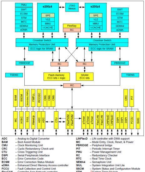
图1.MPC5643L功能框图
评估板KITMPC5643DBEVM
The KITMPC5643DBEVM evaluation board is populated with a MPC5643L safety oriented microcontroller from the Qorivva family. The KITMPC5643DBEVM is a daughter board that extends the KIT33908MBEVBE kit (populated with MC33908 System Basis chip). Together, these two kits create a platform that forms a base for a Safety Ecosystem, which can reach the highest level in functional safety as defined by the ISO26262.
The daughter board includes the MCU and external components necessary for its basic operation as the decoupling capacitors, crystal oscillator, reset circuitry, LED indicators, etc. Power supply and intelligent power management including enhanced safety features is provided to the daughter board from the mother board. Due to this, the daughter board cannot operate separately and it has to be plugged on the mother board (using four 80-pin connectors).
The daughter board is delivered with a demo software already loaded in the Flash memory of the MPC5643L. This code provides algorithms and procedures necessary to initialize and operate the MC33908 correctly. See the KTMPC5643DBSWUG - Basic SW Drivers for MPC5643L and the KTMPC5643DBDEMOUG – MC33908 Driver and Demo SW for details.

图2.评估板KITMPC5643DBEVM外形图
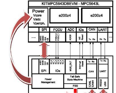
图3.评估板KITMPC5643DBEVM和KIT33908MBEVBE接口图
评估板KITMPC5643DBEVM主要特性:
•Qorivva MPC5643L 32-bit microcontroller with safety architecture
•Preloaded software demo for the MC33908 and MPC5643L platform
•Designed to be plugged onto the KIT33908MBEVBE Evaluation Board
•Separated power supplies for the core and the ADC
•High precision VCCA power supply connected to the ADC reference voltage
•Equipped by Nexus and JTAG for simple Debug
•Possible to connect USB/RS232 through the mother board
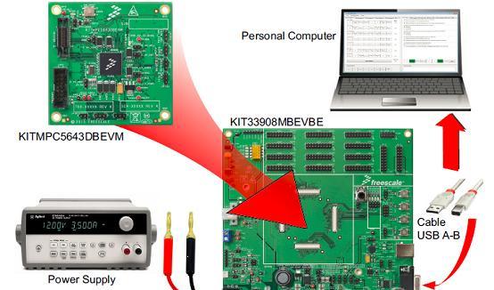
图4.评估板KITMPC5643DBEVM硬件开发配置图
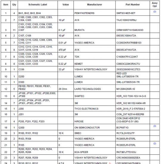
评估板KITMPC5643DBEVM材料清单:

采用MPC5643L MCU三相BLDC/PMSM低压电源参考设计MTRCKTDBN5643L
Freescale’s embedded motion control series 3-Phase BLDC/PMSM Low Voltage Power Stage is an8 V–50 V, 10 Amps, surface-mounted power stage. In combination with one of the embedded motioncontrol series controller boards, it provides a software development platform that allows algorithms to bewritten and tested without the need to design and build a power stage. It supports speed and positionsensing based on Hall sensors, resolver sensors, encoder sensors, and back electromotive force(BackEMF) signals for sensorless control.
The 3-Phase BLDC/PMSM Low Voltage Power Stage has an over-current protection. It is independent ofthe control board when you choose the internal MC33937A DC bus operational amplifier with anover-current comparator. You must therefore be careful when you drive low impedance motors. Thecurrent measuring circuitry is setup for ±10 Amps full scale. At ambient temperature (25 °C), the boardremains within thermal limits when operating with output currents of up to 10 Amps continuous RMS.
Input connections are made via the 40-pin and 10-pin ribbon cable connectors J3 and J4. Pin assignmentsfor the input connector. Power connections to the motorare made on the 3-way connectors J6 (Phase A), J7 (Phase B), and J8 (Phase C). The input voltagerequirements are met by a power supply of 8 V–50 V. The voltage should be within these limits. The boardsustains a voltage of at least 8 V with a maximum of 58 V. The input power is supplied by means of the2.1 mm jack connector J2 or clamp connector J1.
低压电源参考设计MTRCKTDBN5643L主要特性:
• MC33937A MOSFET pre-driver
• Motor control interface:
— UNI-3
— MC33937A pre-driver
• Braking chopper circuit
• Phase and DC-Bus voltage and current sensing circuits
• DC-Bus over current protection
• +12 Vdc, +5 Vdc DC-DC converters
责任编辑:HanFeng
【免责声明】
1、本文内容、数据、图表等来源于网络引用或其他公开资料,版权归属原作者、原发表出处。若版权所有方对本文的引用持有异议,请联系拍明芯城(marketing@iczoom.com),本方将及时处理。
2、本文的引用仅供读者交流学习使用,不涉及商业目的。
3、本文内容仅代表作者观点,拍明芯城不对内容的准确性、可靠性或完整性提供明示或暗示的保证。读者阅读本文后做出的决定或行为,是基于自主意愿和独立判断做出的,请读者明确相关结果。
4、如需转载本方拥有版权的文章,请联系拍明芯城(marketing@iczoom.com)注明“转载原因”。未经允许私自转载拍明芯城将保留追究其法律责任的权利。
拍明芯城拥有对此声明的最终解释权。
相关资讯
:
基于MC33771主控芯片的新能源锂电池管理系统解决方案

AMIC110 32位Sitara ARM MCU开发方案

基于AMIC110多协议可编程工业通信处理器的32位Sitara ARM MCU开发方案

基于展讯SC9820超低成本LTE芯片平台的儿童智能手表解决方案

基于TI公司的AM437x双照相机参考设计

基于MTK6580芯片的W2智能手表解决方案


 2012- 2022 拍明芯城ICZOOM.com 版权所有 客服热线:400-693-8369 (9:00-18:00)


