ADI ADAR1000四路8GHz-16GHz波束形成解决方案
 375
375
 拍明
拍明
原标题:ADI ADAR1000四路8GHz-16GHz波束形成解决方案
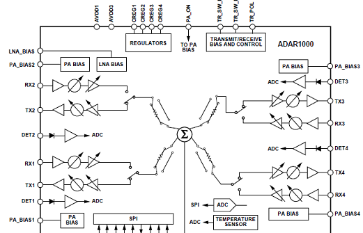
ADI公司的ADAR1000是四路X波段和Ku波段(8GHz-16GH)z波束形成核集成电路,器件在接收和发送模式间半双工模式.接收模式,输入信号通过四路接收通路在RF_IO引脚组合,发送模式,RF_IO输入信号分列并通过四路发送通路.在两种模式,提供≥31 dB增益调整范围和360°相位调整范围,分辨率优于6比特(≤0.5 dB 和2.8°).集成了四路-20dbm到+10dBM功率检测器和温度传感器,四线SPI接口.主要用在相控阵雷达和卫星通信系统.本文介绍了ADAR1000主要特性和功能框图,以及评估板ADAR1000-EVALZ主要特性,连接图,电路图和PCB设计图.
The ADAR1000 is a 4-channel, X and Ku frequency band, beamforming core chip for phased arrays. This device operates in half-duplex between receive and transmit modes. In receive mode, input signals pass through four receive channels and are combined in a common RF_IO pin. In transmit mode, the RF_IO input signal is split and passes through the four transmit channels. In both modes, the ADAR1000 provides a ≥31 dB gain adjustment range and a full 360° phase adjustment range in the radio frequency (RF) path, with better than 6-bit resolution (less than ≤0.5 dB and 2.8°, respectively).
Control of all the on-chip registers is through a simple 4-wire serial port interface (SPI). In addition, two address pins allow SPI control of up to four devices on the same serial lines. Additionally, dedicated transmit and receive load pins provide synchronization of all core chips in the same array, and a single pin controls fast switching between the transmit and receive modes.
The ADAR1000 is available in a compact, 88-terminal, 7 mm×7 mm, LGA package and is specified from −40℃ to +85℃.
ADAR1000主要特性:
8 GHz to 16 GHz frequency range
Half-duplex for transmit and receive modes
Single-pin transmit and receive control
360° phase adjustment range
2.8° phase resolution
≥31 dB gain adjustment range
≤0.5 dB gain resolution
Bias and control for external transmit and receive modules
Memory for 121 prestored beam positions
Four −20 dBm to +10 dBm power detectors
Integrated temperature sensor
Integrated 8-bit ADC for power detectors and temperature sensor
Programmable bias modes
4-wire SPI interface
ADAR1000应用:
Phased array radar
Satellite communications systems

图1.ADAR1000功能框图
评估板ADAR1000-EVALZ
The ADAR1000-EVALZ evaluation board is designed for evaluating the performance of the ADAR1000, a 4-channel, X band and Ku band beamforming core chip for radar systems. All the radio frequency (RF) input/output channels and detector inputs are brought out to Subminiature Version A (SMA) connectors. On-board logic level translators convert the on-chip 1.8 V logic signals to 3.3 V for interfacing to external controllers running on 3.3 V. Two identical 20-pin, dual row rectangular headers provide the digital interface signals to allow daisy-chaining up to four ADAR1000-EVALZ evaluation boards together. A 24-pin connector provides control and bias outputs to interface to four external transmit and receive (T/R) modules with each ADAR1000-EVALZ evaluation board.
The ADAR1000-EVALZ evaluation board can be used with an Analog Devices, Inc., system demonstration platform (SDP) SDP-S or SDP-B board (supplied separately), which allows connection to a Microsoft Windows®-based PC through the USB for controlling of all the ADAR1000 device functions.
For full details on the ADAR1000, see the ADAR1000 data sheet, which should be consulted in conjunction with this user guide when using this evaluation board.
评估板ADAR1000-EVALZ主要特性:
Based on the ADAR1000 4-channel beamformer core chip
Controllable through SPI
Multiple forms of digital interface (3.3 V and 1.8 V logic)
On-board logic level translators with 1.8 V low dropout regulator for supply
Software control from a Windows-based PC through USB

图2.评估板ADAR1000-EVALZ外形图
详情请见:
责任编辑:HanFeng
【免责声明】
1、本文内容、数据、图表等来源于网络引用或其他公开资料,版权归属原作者、原发表出处。若版权所有方对本文的引用持有异议,请联系拍明芯城(marketing@iczoom.com),本方将及时处理。
2、本文的引用仅供读者交流学习使用,不涉及商业目的。
3、本文内容仅代表作者观点,拍明芯城不对内容的准确性、可靠性或完整性提供明示或暗示的保证。读者阅读本文后做出的决定或行为,是基于自主意愿和独立判断做出的,请读者明确相关结果。
4、如需转载本方拥有版权的文章,请联系拍明芯城(marketing@iczoom.com)注明“转载原因”。未经允许私自转载拍明芯城将保留追究其法律责任的权利。
拍明芯城拥有对此声明的最终解释权。


 产品分类
产品分类


 2012- 2022 拍明芯城ICZOOM.com 版权所有 客服热线:400-693-8369 (9:00-18:00)


