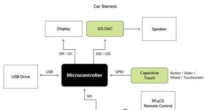
基于Atmel ATR4251C主控芯片的射频性能卓越的汽车音响解决方案
 291
291
 拍明
拍明
定制开发
应用领域:汽车电子
方案类型:原型方案
主控芯片:ATR4251C
方案概述
Atmel 拥有 30 多年的无线广播芯片设计经验 。 现在作为一家供应商 , 本公司为快速扩展的 AM / FM 有源天线市场提供具有顶尖性能 、 灵活性和高集成度的集成电路解决方案 。 公司具备精深的专业知识以及 ISO9001 和 ISO16949 质量标准 , 能够满足您对于汽车无线电市场的质量和性能需求 。 近年来 , Atmel 已经推出过几代知名产品 。

特性和优势
高度集成的产品具有顶尖的质量水准和卓越的射频性能 。
高度集成 、 功能丰富且稳定的 AM / FM 天线放大器集成电路在各种解决方案中具备很多优势 。
无论是杆式天线 、 鲨鱼鳍天线 、 短杆天线还是车窗天线 , 都可以使用 Atmel 天线设备 。
ATR4251C
Low-noise AM/FM antenna amplifier, high dynamic range for AM and FM, AGC for AM and FM, high intercept point 3rd-order for FM, FM amplifier adjustable for various cable impedances, high intercept point 2nd- and 3rd-order for AM, low-output impedance for AM, low power consumption
Features
● High dynamic range for AM and FM
● Integrated AGC for AM and FM
● High intercept point 3rd order for FM
● FM amplifier adjustable to various cable impedances
● High intercept point 2nd and 3rd order for AM
● Low noise output voltage
● Low power consumption
● Low output impedance AM
参数
Automotive Qualified:Yes
Temp. Range (deg C):-40 to 105
Pin Count:24
Functional Description
The Atmel® ATR4251C is an integrated AM/FM antenna impedance matching circuit. It compensates cable losses betweenthe antenna (for example windshield, roof, or bumper antennas) and the car radio which is usually placed far away from theantenna.
AM refers to the long wave (LW), medium wave (MW) and short wave (SW) frequency bands (150kHz to 30MHz) that are usually used for AM transmission, and FM means any of the frequency bands used world-wide for FM radio broadcast(70MHz to 110MHz).
Two separate amplifiers are used for AM and FM due to the different operating frequencies and requirements in the AM and FM band. This allows the use of separate antennas (for example, windshield antennas) for AM and FM. Of course, both amplifiers can also be connected to one antenna (for example, the roof antenna).
Both amplifiers have automatic gain control (AGC) circuits in order to avoid overdriving the amplifiers under large-signal conditions. The two separate AGC circuits prevent strong AM signals from blocking FM stations, and vice versa.
3.1 AM Amplifier
Due to the long wavelength in AM bands, the antennas used for AM reception in automotive applications must be short compared to the wavelength. Therefore these antennas do not provide 50Ω output impedance, but have an output impedance of some pF. If these (passive) antennas are connected to the car radio by a long cable, the capacitive load of this cable (some 100pF) dramatically reduces the signal level at the tuner input.
In order to overcome this problem, Atmel ATR4251C provides an AM buffer amplifier with low input capacitance (less than 2.5pF) and low output impedance (5Ω). The low input capacitance of the amplifier reduces the capacitive load at the antenna, and the low impedance output driver is able to drive the capacitive load of the cable. The voltage gain of the amplifier is close to 1 (0dB), but the insertion gain that is achieved when the buffer amplifier is inserted between antenna output and cable may be much higher (35dB). The actual value depends, of course, on antenna and cable impedance.
The input of the amplifier is connected by an external 4.7MΩ resistor to the bias voltage (pin 7, SSO20) in order to achieve high input impedance and low noise voltage.
AM tuners in car radios usually use PIN diode attenuators at their input. These PIN diode attenuators attenuate the signal by reducing the input impedance of the tuner. Therefore, a series resistor is used at the AM amplifier output in the standard application. This series resistor guarantees a well-defined source impedance for the radio tuner and protects the output of the AM amplifier from short circuit by the PIN diode attenuator in the car radio.
3.2 AM AGC
The IC is equipped with an AM AGC capability to prevent overdriving of the amplifier in case the amplifier operates near strong antenna signal level, for example, transmitters. The AM amplifier output AMOUT1 is applied to a resistive voltage divider. This divided signal is applied to the AGC level detector input pin AGCAMIN. The rectified signal is compared against an internal reference. The threshold of the AGC can be adjusted by adjusting the divider ratio of the external voltage divider. If the threshold is reached, pin AGCAM opens an external transistor which controls PIN diode currents and limits the antenna signal and thereby prevents overdriving the AM amplifier IC.
3.3 FM Amplifier
The FM amplifier is realized with a single NPN transistor. This allows use of an amplifier configuration optimized on the requirements. For low-cost applications, the common emitter configuration provides good performance at reasonable bills of materials (BOM) cost(1). For high-end applications, common base configuration with lossless transformer feedback provides a high IP3 and a low noise figure at reasonable current consumption(2). In both configurations, gain, input, and output impedance can be adjusted by modification of external components.
The temperature compensated bias voltage (VREF1) for the base of the NPN transistor is derived from an integrated band gap reference. The bias current of the FM amplifier is defined by an external resistor.
Notes: 1. See test circuit (Figure 8-1 on page 11)2. See application circuit (Figure 9-1 on page 12)ATR4251C [DATASHEET] 9258E–AUDR–11/14 6
3.4 FM/TV AGC
The IC is equipped with an AGC capability to prevent overdriving the amplifier in cases when the amplifier is operated with strong antenna signals (for example, near transmitters). It is possible to realize an external TV antenna amplifier with integrated AGC and external RF transistor. The bandwidth of the integrated AGC circuit is 900MHz. FM amplifier output FMOUT is connected to a capacitive voltage divider and the divided signal is applied to the AGC level detector at pin AGCIN. This level detector input is optimized for low distortion. The rectified signal is compared against an internal reference. The threshold of the AGC can be adjusted by adjusting the divider ratio of the external voltage divider. If the threshold is reached, pin AGC1 opens an external transistor which controls the PIN diode current, this limits the amplifier input signal level and prevents overdriving the FM amplifier
汽车音响
汽车音响(auto audio) 为减轻驾驶员和乘员旅行中的枯燥感而设置的收放音装置。最早使用的是汽车调幅收音机,后来是调幅调频收音机、磁带放音机,发展至CD放音机和兼容DCC、DAT数码音响。现在汽车音响无论在音色、操作和防振等各方面均达到了较高的标准,能应付汽车在崎岖的道路上颠簸,保证性能的稳定和音质的完美。

分类
按汽车出厂时音响的时间分
按汽车出厂的时间分为原配产品和售后产品。原配产品是指原厂配套的产品,就是车主在买到车的时候已经装在汽车面板的音响,不同档次的汽车选择不同档次的品牌与之搭配。但是无论选择什么品牌,其音响的功能和音质都受到限制(除特别顶级的汽车之外)原因是汽车制造商从安全角度考虑必须将汽车音响按键设计得较大,音响的功能也必须经过长时间的考验才同意使用(某些先进的功能不能使用,因为没有经过长时间的考验)。
售后产品是指消费者买主车之后对汽车音响不满意,更换时选择的音响。由于不受车厂限制,所以可以用八仙过海、各显神通来形容。
按汽车音响品牌的地域分
按汽车音响品牌的地域分,可分为日本品牌和欧美品牌。这也是大家比较熟悉的分类,家用音响也经常以这种分类来比较优劣。
日本品牌的音响以对音质的读取和修饰见长。声音的读取是指主机从数字和模拟音源获取信号的过程。日本品牌的音响这方面技术非常成熟,音质纯正细腻。对音质的修饰是指运用数学手段制造各种场场效果以取悦人耳,如BBE、DHE、各种场场模拟等,这些功能打破了音源的本色,但是比较符合人耳的习惯,所以非常取悦于消费者。总体来说,绝大数日本音响的音质总体比较平衡,符合大众的消费。
欧美品牌的音响以功率放大中的真实还原和低间震撼见长。欧美人注重真实还原音乐的本色,同时某些厂家又特别注重低音。在家用音响中欧美品牌的功放和音箱比较受推崇。
按汽车音响厂家生产专一性分
按汽车音响厂家专一性来分,可分为只生产汽车音响的专业厂家和既生产汽车音响又生产其他家电产品的广域产品生产厂家,如果调试不当可能还不及被动分音的平衡性更耐听。
历史发展
虽然音响设备对于轿车来讲,只是一种辅助性设备,对车子的运行性能没有影响。但随着人们对享受的要求越来越高,汽车制造商也日益重视起轿车的音响设备,并将它做为评价轿车舒适性的依据之一。轿车音响的发展史也是电子技术的发展史,电子技术的每项重大的技术进步都推动着轿车音响的发展。早在1923年美国首先出现了装配无线电收音机的轿车,随后许多轿车都步其后尘 ,在仪表板总成上安装了无线电收音机。这时候车用无线电收音机都是用电子管,直到50年代 出现半导体技术后,轿车收音机出现了技术革命,用半导体管逐步取替了电子管,提高了轿车收音机的寿命。70年代初,卡式收录机进入了市场,一种可播放卡式录音带的车用收放两用机 出现在轿车上,同时机芯开始应用集成电路。直至80年代末,一般轿车的音响多以一个卡式收放两用机与一对扬声器为基础组合,扬声器分左右两路声道,有的置于仪表板总成的两侧,有的置于车门,有的置于后座的后方,收放两用机输出功率多在20瓦左右。
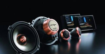
今天,轿车音响又进入了一个新的里程,向大功率多路输出、多喇叭环回音响、多喋式镭射CD等方向发展。世界音响制造商也将轿车音响辟为一个专门的工业部门,针对轿车的特殊环境,充分考虑车厢的音响效果,采用高新技术制造轿车音响设备,其播送的音响效果完全能与家用音响相媲美。日本凌志LS400型轿车的AM/FM音响系统就有5个放大器,配有7个分频喇叭,包括2个拱形高频喇叭,4个宽频带喇叭和一个后装式8寸低频喇叭,使整个车厢充满了立体音的环回感受。
市面上已经有各种供轿车专用的高级音响设备,一些汽车音响爱好者将大功率放大器和电子网络器安置在轿车行李箱内,将超低音大口径喇叭和其它型号喇叭分别嵌入后窗下围板和车门板上,使用独立的直流电源,功率输出达上百瓦以上,音色浑厚优美,高低有错,把车厢内狭小的空间变成了令人愉快的音乐欣赏室,予人以美的享受。
汽车的运行环境是十分恶劣的,包括振动、高温、噪音、电磁波等都会干扰车内电子设备的正常工作,因此轿车专用的音响设备不论从设计和工艺制造方面的要求都要比家用音响严格 ,而且价格不菲,从这个意义上讲,高性能的轿车音响实际上是当今音响世界中的顶级品。
责任编辑:Davia
【免责声明】
1、本文内容、数据、图表等来源于网络引用或其他公开资料,版权归属原作者、原发表出处。若版权所有方对本文的引用持有异议,请联系拍明芯城(marketing@iczoom.com),本方将及时处理。
2、本文的引用仅供读者交流学习使用,不涉及商业目的。
3、本文内容仅代表作者观点,拍明芯城不对内容的准确性、可靠性或完整性提供明示或暗示的保证。读者阅读本文后做出的决定或行为,是基于自主意愿和独立判断做出的,请读者明确相关结果。
4、如需转载本方拥有版权的文章,请联系拍明芯城(marketing@iczoom.com)注明“转载原因”。未经允许私自转载拍明芯城将保留追究其法律责任的权利。
拍明芯城拥有对此声明的最终解释权。


 产品分类
产品分类


 2012- 2022 拍明芯城ICZOOM.com 版权所有 客服热线:400-693-8369 (9:00-18:00)


