基于Freescale公司的Kinetis KEA128三相无传感器BLDC马达控制参考设计
 132
132
 拍明
拍明
原标题:Freescale Kinetis KEA128三相无传感器BLDC马达控制参考设计
freescale公司的Kinetis KEA系列是基于ARM Cortex-M0+核的MCU,工作频率高达48MHz,工作电压2.7-5.5V,工作温度–40℃到 +125℃.器件包括一套模拟,通信,定时和控制外设以及闪存和不同的引脚,具有很好的ESD/EMC性能,非常适合汽车应用.本文介绍了Kinetis KEA128主要特性,框图, 模块内部连接配置图以及KEA128BLDCRD三相无传感器BLDC马达控制参考设计主要特性,电路图和材料清单.
Kinetis EA series MCUs for automotive provide cost-effective ARM®-based solution for a wide range of automotive applications and are pin-compatible across the Kinetis EA series and with future Kinetis automotive families.
This series includes a set of analog, communication, timing and control peripherals with varying flash memory size and pin count. These scalable devices are highly robust, and offer an enhanced ESD/EMC performance solution for cost-sensitive automotive applications. This series is supported by development tools, software and hardware references to help you quickly start designing.
Kinetis KEA128主要特性:
Operating Characteristics
• Voltage range: 2.7 to 5.5 V
• Flash write voltage range: 2.7 to 5.5 V
• Temperature range (ambient): –40 ℃ to +125 ℃
Performance
• Up to 48 MHz ARM Cortex-M0+ core
• Single-cycle 32-bit x 32-bit multiplier
• Single-cycle I/O access port
Memories and Memory Interfaces
• Up to 128 KB flash
• Up to 256 B EEPROM
• Up to 16 KB RAM
Clocks
• Oscillator (OSC)—loop-controlled Pierce oscillator, crystal or ceramic resonator range of 31.25 kHz to 39.0625 kHz or 4 MHz to 24 MHz
• Internal clock source (ICS)—internal FLL with internal or external reference, precision trimming of internal reference allowing 1% deviation across temperature range of –30 ℃ to 85 ℃ and 1.5% deviation across temperature range of –40 ℃ to 125 ℃, up to 48 MHz
• Internal 1 kHz low-power oscillator (LPO)
System Peripherals
• Power management module (PMC) with three power modes: run, wait, stop
• Low-voltage detection (LVD) with reset or interrupt, selectable trip points
• Watchdog with independent clock source (WDOG)
• Programmable cyclic redundancy check module (CRC)
• Serial wire debug interface (SWD)
• Bit manipulation engine (BME)
Security and Integrity Modules
• 80-bit unique identification (ID) number per chip
Human-machine interface (HMI)
• Up to 71 general-purpose input/output (GPIO)
• Up to two 32-bit keyboard interrupt modules (KBI)
• External interrupt (IRQ)
Analog Modules
• One 12 bit with up to 16 channel SAR ADC with internal band gap reference channel, operation in stop mode, optional hardware trigger (ADC)
• Two analog comparators containing a 6-bit DAC and programmable reference input (ACMP)
Timers
• One 6-channel FlexTimer/PWM (FTM)
• Up to two 2-channel FlexTimer/PWM (FTM)
• One 2-channel periodic interrupt timer (PIT)
• One real-time clock (RTC)
• Up to one 16-bit pulse width timer
Target Applications
• Infotainment connection module
• Park assistance
• DC/BLDC motor control
• Electronic park brake
• TPMS
• Motorcycle CDI/EFI
• Battery management
• Pump/fan controller
• Passive entry push start
• Ambient lighting
• BCM/HVAC
• Windows/door/sun roof
• Seats/mirror/wiper
• Immobilizer
• Powertrain companion chip
• Generic sensor node
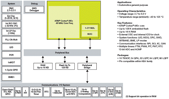
图1. Kinetis KEA128框图

图2.模块内部连接配置图
KEA128BLDCRD三相无传感器BLDC马达控制参考设计
This reference manual describes the design of a 3-phase brushless DC (BLDC) motor control drive using a sensorless algorithm. The design is targeted at automotive applications, such as:
•Heating, ventilation, and air conditioning (HVAC)
•Electric pumps, motor control, and auxiliaries
•Transmission and gearbox
•Doors, window lift, and seat control
The design exhibits the suitability and advantages of the Kinetis KEA128 microcontroller for BLDC motor control. It serves as an example of a BLDC motor control design using the general-purpose Kinetis EA series of microcontrollers.
The overall solution is based on the Kinetis KEA128 ARM® Cortex®-M0+ automotive-grade microcontroller, MC33937A FET pre-driver, and MC33903D system basis chip. This Freescale integrated circuit eco-system represents a BLDC motor control solution for the 12 V automotive systems.
The motor control reference design is based on a Kinetis KEA128 32-bit ARM® Cortex®-M0+ automotive MCU and is an example of a 3-phase sensorless brushless DC (BLDC) motor control solution using a six-step commutation process, including closed-loop speed control and dynamic motor current limitation.
The overall hardware solution consists of the Kinetis KEA128 MCU, MC33903D system basis chip, and MC33937A 3-phase field effect transistor pre-driver. This Freescale integrated circuit eco-system represents a BLDC motor control solution for the 12 V automotive systems.
The motor control application is built upon the algorithm building blocks provided by the Automotive Math and Motor Control Library Set for ARM® Cortex®-M0+. These include 16-bit and 32-bit fixed point arithmetic based elemental mathematical functions, PI controlers, and digital filters.
Application data visualization and control is provided by the FreeMASTER run-time debugging tool. Integrated Motor Control Application Tuning (MCAT) tool allows run-time tuning of the application parameters.
The reference design is available for purchase in the package including the reference design hardware board and 3-phase BLDC motor.
KEA128BLDCRD参考设计主要特性:
• 32-bit KEA128 MCU
• MC33937A FET pre-driver
• MC33903D system basis chip
• Sensorless control using back-EMF zero-crossing detection
• DC-bus overvoltage, undervoltage, and overcurrent fault detection
• Application built using the Automotive Math and Motor Control Library Set functions
• FreeMASTER tool for instrumentation/visualization
• Integrated Motor Control Application Tuning (MCAT) tool
• LIN & CAN connectivity support
• OpenSDA debug interface
KEA128BLDCRD参考设计包括:
KEA128BLDCRD DVD
TKEA128BLDCRD Quick Start Guide
3-phase BLDC motor
KEA128BLDCRD Board
USB cable
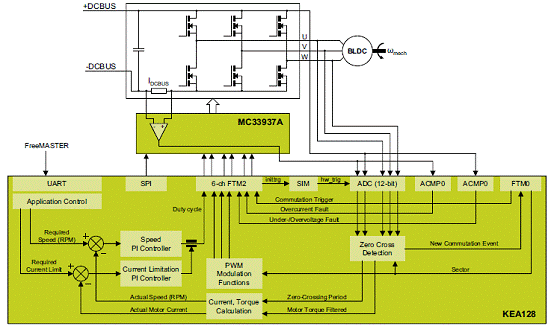
图3. KEA128BLDCRD参考设计系统框图
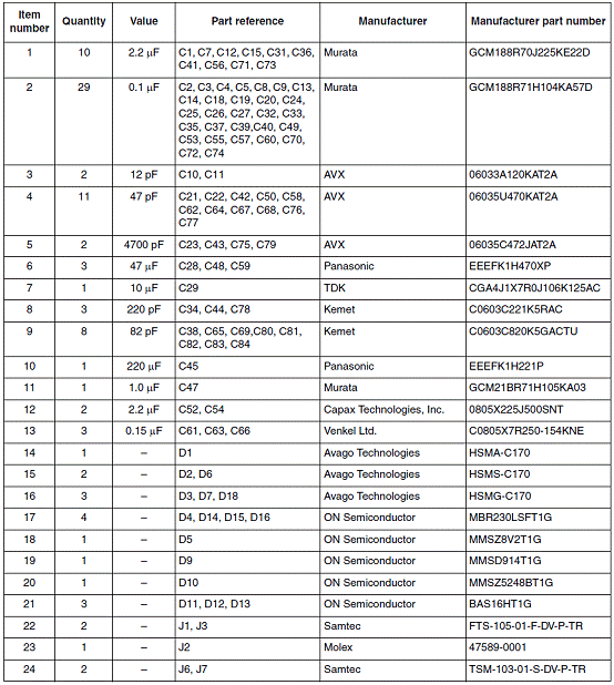
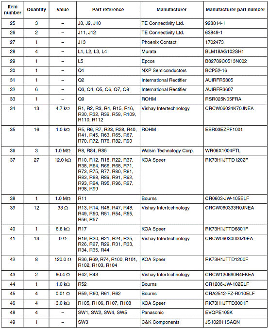
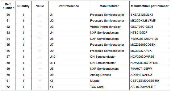
KEA128BLDCRD参考设计材料清单:
责任编辑:HanFeng
【免责声明】
1、本文内容、数据、图表等来源于网络引用或其他公开资料,版权归属原作者、原发表出处。若版权所有方对本文的引用持有异议,请联系拍明芯城(marketing@iczoom.com),本方将及时处理。
2、本文的引用仅供读者交流学习使用,不涉及商业目的。
3、本文内容仅代表作者观点,拍明芯城不对内容的准确性、可靠性或完整性提供明示或暗示的保证。读者阅读本文后做出的决定或行为,是基于自主意愿和独立判断做出的,请读者明确相关结果。
4、如需转载本方拥有版权的文章,请联系拍明芯城(marketing@iczoom.com)注明“转载原因”。未经允许私自转载拍明芯城将保留追究其法律责任的权利。
拍明芯城拥有对此声明的最终解释权。


 产品分类
产品分类


 2012- 2022 拍明芯城ICZOOM.com 版权所有 客服热线:400-693-8369 (9:00-18:00)


