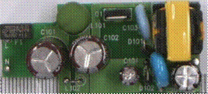
基于低功率LED照明趋势解决方案
 119
119
 拍明
拍明
原标题:低功率 LED 照明趋势解决方案-第四部分
A19, E14 / 17, E26 / 27 bulb LED Driver Design
LED lighting trend in our blog series, we discussed the MR11 / 16 LED driver design problems. Now, let’s look at A19, E14 / 17, E26 / 27 bulb LED driver designs.
Some bulb type is called “screw caps” and “candle light.” Most with CFL or LED incandescent replacement, has won the majority of application requirements.
A19, E14 / 17, E26 / 27 screw bulb structure
Input voltage directly from the AC power socket type: E14 / 17 (Candle), A19 / E26 / 27 (screw type) (for candle lamp, rated 1~5W; to replace incandescent lamps, rated power 4~17W.) dimensions shown in Figure 1 and Figure 2.

Figure 1. Example candle lamps ((L: 99 毫米, D: 26 毫米, E: 17 mm) of

Figure 2. Example Edison light bulb (L: 105 毫米, D: 55 毫米, B: 26 mm) of
A19, E14 / 17, E26 / 27 screw bulb LED Driver Design Challenge
For candle lights, the LED driver design challenge is a small printed circuit board space. The printed circuit board space is less than the MR lamp space, and works in AC input voltage source. With LED driver designed to replace incandescent lamps, which printed circuit board space than a candle lamp or lamps MR large, rated power is large, and therefore LED driver as well. Printed circuit board space is limited, like candle lamp. For screw bulb design, power factor and total harmonic distortion is almost mandatory requirements, there are additional dimmers operating requirements.
For a lamp holder side parabolic E26 / 27 bulbs, printed circuit board dimensions of lampholders side: 20 mm; LED module side: 35 mm; width: 70 mm (see FIG. 3 ) .


Figure 3. E26 / E27 PCB Dimensions Example
It must be greater than 75% efficiency. Dimmer compatible with a variety of design requirements include holding current, in a wide range of optical amplitude linear manner, and without blinking.
A19, E14 / 17, E26 / 27 screw bulb Fairchild Solutions
In terms of security, isolated drive is preferred. In this power range, the preferred LED driver solution is flyback topology. For candle lights, power factor and total harmonic distortion, although low-power applications, but still mandatory. Many designers use a single-stage flyback solutions. Single-stage power factor correction flyback topology reduces the printed circuit board size, because it eliminates the need for bulky input electrolytic capacitor. Use a single-stage primary side regulation (PSR) flyback solutions can further reduce the number of components. With its low bill of materials (BOM) cost, isolation, power factor correction and a wide input voltage range, PFC PSR flyback topology is expected to become the first choice of LED driver topologies.
Table 1. Fairchild primary side regulation controller

In PSR topology without secondary-side feedback, so no optical isolator, the error amplifier (eg TL431), as well as compensation and biasing resistors and capacitors. Figure 4 shows a simplified schematic of PSR.

Figure 4. Schematic primary side regulation
Advantage of primary side regulation flyback topology include:
· Single-level solutions limit the number of components and eventually for smaller design space.
· FL103 50kHz operating switching frequency helps flyback transformer magnetic for volume-constrained applications.
· Integrated MOSFET having FSEZ1317 reduces the number of components, thus saving additional printed circuit board space.
· Primary side regulation topology element to reduce help address pressure to reduce costs.
· Without secondary feedback circuitry, which will immediately reduce the number of components and improve reliability (eliminating the need for optical isolators or TL431).
· Fairchild’s PSR topologies include TRUECURRENT ™ technology, the industry-leading performance constant <± 3%, to provide consistent, high-quality light irradiation.
· Solutions have been adopted isolation mode.
· Single-stage flyback topology can meet
the power factor and total harmonic distortion requirements.
Primary side regulation flyback topology operates in two modes: constant voltage (CV) and constant current (CC). LED drive should run in constant current mode, in order to better control the LED string lighting luminance output. Figure 5 shows the PSR flyback regulator IV characteristics.

Figure 5. The primary side regulation flyback LED driver output characteristics IV
PSR preferably discontinuous conduction mode (DCM), because this mode supports better output regulation. Typical waveforms shown in FIG. 6.

Figure 6. DCM flyback converter waveforms
When operating at a constant voltage regulation mode, the current in the inductor discharge time t DIS period, the output voltage and diode forward voltage drop, and will be reflected back to the auxiliary winding end. Since the diode forward voltage drop and decrease with the current decrease, the auxiliary winding voltage reflects the diode conduction time t DISat the end of the output voltage. Through the end of the diode conduction time auxiliary winding voltage is sampled, the output voltage information can be obtained.
When operating at constant current regulation mode, peak drain current I PEAK and inductor current discharge time t DIS to estimate the output current because the output current is in a stable state and the average diode current is the same. Using Fairchild’s TRUECURRENT ™ technology, constant current output can be obtained more accurately controlled.
责任编辑:HanFeng
【免责声明】
1、本文内容、数据、图表等来源于网络引用或其他公开资料,版权归属原作者、原发表出处。若版权所有方对本文的引用持有异议,请联系拍明芯城(marketing@iczoom.com),本方将及时处理。
2、本文的引用仅供读者交流学习使用,不涉及商业目的。
3、本文内容仅代表作者观点,拍明芯城不对内容的准确性、可靠性或完整性提供明示或暗示的保证。读者阅读本文后做出的决定或行为,是基于自主意愿和独立判断做出的,请读者明确相关结果。
4、如需转载本方拥有版权的文章,请联系拍明芯城(marketing@iczoom.com)注明“转载原因”。未经允许私自转载拍明芯城将保留追究其法律责任的权利。
拍明芯城拥有对此声明的最终解释权。


 产品分类
产品分类


 2012- 2022 拍明芯城ICZOOM.com 版权所有 客服热线:400-693-8369 (9:00-18:00)


