基于IDT公司的ZMID5202电感位置传感器旋转360度解决方案
 240
240
 拍明
拍明
原标题:IDT ZMID5202电感位置传感器旋转360度解决方案
IDT公司的ZMID520x系列是电感式位置传感器,采用线回路和涡流产生电感的原理来检测导电物体在线圈上滑动或旋转的位置,旋转检测全方位360度,PWM数字输出,过压,反相极性,ESD和短路保护,10位分辨率,满足汽车标准AEC-Q 100, grade 0,工作温度-40°C 到150°C,主要用在高达360度的旋转位置传感器如转向角传感器,替换电位器,小角度传感器或弧线运动传感器如阀门传感器,汽车水平传感器以及线性运动传感器如液面传感器.本文介绍了ZMID520x系列主要特性,功能框图,应用电路以及评估板ZMID520x EVK主要特性,主要元件分布图,ZMID5201/02/03演示板电路图,材料清单和PCB设计图.
The ZMID520x uses the physical principles of induction in a wire loop and eddy currents to detect the position of an electrically conducting target that is sliding or rotating above a set of coils, consisting of one transmitter coil and two receiver coils.
The three coils are typically printed as copper traces on a printed circuit board (PCB). They are arranged such that the transmitter coil induces a secondary voltage in the receiver coils that depends on the position of the metallic target above the coils.
A signal representative of the target’s position over the coils is obtained by demodulating and processing the secondary voltages from the receiver coils. The target can be any kind of metal, such as aluminum, steel or a PCB with a printed copper layer.
The ZMID5202 is an inductive position sensor IC with PWM output, used for absolute rotary and linear motion sensing in automotive, industrial and consumer applications. The ZMID5202 uses the physical principles of induction in a wire loop and eddy currents to detect the position of a metallic target that is sliding or rotating above a set of coils, consisting of one transmitter coil and two receiver coils. The three coils are typically printed as copper traces on a printed circuit board (PCB). They are arranged such that the transmitter coil induces a secondary voltage in the receiver coils which depends on the position of the metallic target above the coils. After demodulating and processing the secondary voltages from the receiver coils, a signal representative of the metallic target’s position over the coils is obtained.
The ZMID5201/-02-/03 ICs are fully qualified to the automotive standard AEC-Q 100, grade 0 from -40°C up to 150°C ambient temperature.
ZMID5202主要特性:
Inductive principle
Rotation sensing up to a full turn of 360º
PWM digital output
Overvoltage, reverse polarity, ESD and short circuit protection
10-bit resolution
Power or ground loss detection
Facilitates redundant design requirements
Programmable linearity correction
Adaptive gain control supporting a wide range of coil designs
Diagnostic features supporting ISO26262
Supporting up to ASIL-B
Overvoltage and reverse polarity protection up to ±18V
Small 14-TSSOP package
The ZMID520x Evaluation Kit is designed for sensor module evaluation,
laboratory setup, and module calibration development for
the ZMID520x Family of Inductive Position Sensor ICs.
ZMID5201: analog interface
ZMID5202: PWM interface
ZMID5203: SENT interface
ZMID5202典型应用:
Rotary position sensors up to 360°; e.g. steering angle sensors, potentiometer replacement
Small-angle sensors or arc-motion sensors; e.g. pedal, vehicle level, or valve sensors
Linear motion sensors; e.g. linear-actuator position sensors, fluid-level sensors

图1.ZMID5202功能框图
主要框图包括:
Power management: power-on-reset (POR) circuit, low drop-out (LDO) regulators for internal supplies
Oscillator: generation of the transmit coil signal
Analog front-end: demodulator and gain control for the receive signals
Analog-to-digital converter (ADC): conversion into digital domain
Digital signal processing: offset correction, conversion of sine and cosine signals into angle and magnitude, angle range adjustment, linearization, etc.
EEPROM: nonvolatile storage of factory and user-programmable settings
One-wire interface (OWI): programming of the chip through the output pin
Interface options:
— Analog output for ZMID5201
— PWM output for ZMID5202
— SENT output for ZMID5203
Protection: overvoltage, reverse polarity , short circuit protection
Test control: factory testing; connect TEST_D and TEST_ENA pins

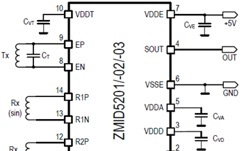
图2.ZMID5202应用电路
评估板ZMID520x EVK
The main purpose of the ZMID520x Evaluation Kit is communicationbetween the user’s computer and the ZMID520x. The computersends commands and data via its USB port to the ZMIDCommunication Board.
The microcontroller on the Communication Board interprets thesecommands and relays them to the ZMID520x located on theZMID520x Demo Board using the one-wire interface (OWI) communicationinterface.
The microcontroller also forwards data bytes from the ZMID520xback to the computer via the USB connection. These bytes canbe sensor readings, raw analog-to-digital converter (ADC) datafrom analog outputs, or ZMID520x EEPROM contents.
The ZMID520x AID EVK Application Software is a graphical userinterface (GUI) is provided online for the kit. It supports allZMID520x configurations and enables the user to intuitivelyunderstand the functionality of the ZMID520x as well asperforming measurements.
The ZMID520x Evaluation Kit is designed for sensor module evaluation,laboratory setup, and module calibration development forthe ZMID520x Family of Inductive Position Sensor ICs.
ZMID5201: analog interface
ZMID5202: PWM interface
ZMID5203: SENT interface
The main purpose of the ZMID520x Evaluation Kit is communicationbetween the user’s computer and the ZMID520x. The computersends commands and data via its USB port to the ZMIDCommunication Board.
The microcontroller on the Communication Board interprets thesecommands and relays them to the ZMID520x located on theZMID520x Demo Board using the one-wire interface (OWI) communicationinterface.
The microcontroller also forwards data bytes from the ZMID520xback to the computer via the USB connection. These bytes canbe sensor readings, raw analog-to-digital converter (ADC) datafrom analog outputs, or ZMID520x EEPROM contents.
The ZMID520x AID EVK Application Software is a graphical userinterface (GUI) is provided online for the kit. It supports allZMID520x configurations and enables the user to intuitivelyunderstand the functionality of the ZMID520x as well asperforming measurements.
评估板ZMID520x EVK主要特性:
USB “plug and play” – no driver installation needed
Small ZMID Communication Board: 5cm 8cm
One-wire communication interface (OWI) enables quick andeasy configuration and calibration of the ZMID520x using theuser’s computer
PWM, analog or SENT reading of the output depending onproduct
The design allows easy swapping of ZMID520x Demo Boards
Ability to connect and evaluate an external module board
— No external power supply needed
— External module is supplied from the ZMID520x DemoBoard
评估板ZMID520x EVK包括:
ZMID520x Demo Board with printed sensor coil
ZMID Communication Board
Micro-USB cable
Kit software is available for download from the IDT web site:

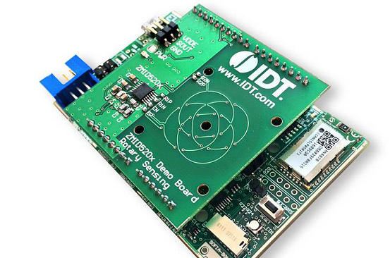
图3. 评估板ZMID520x EVK外形图

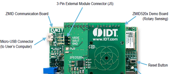
图4. 评估板ZMID520x EVK主要元件分布图

图5. ZMID520x旋转360度演示板概述图
ZMID520x旋转360度演示板材料清单:

详情请见:
![]() IDT_ZMID520x-Datasheet_DST_20170328.pdf
IDT_ZMID520x-Datasheet_DST_20170328.pdf
![]() IDT_ZMID520x-Eval-Kit-User-Manual_MAN_20170327.pdf
IDT_ZMID520x-Eval-Kit-User-Manual_MAN_20170327.pdf
责任编辑:HanFeng
【免责声明】
1、本文内容、数据、图表等来源于网络引用或其他公开资料,版权归属原作者、原发表出处。若版权所有方对本文的引用持有异议,请联系拍明芯城(marketing@iczoom.com),本方将及时处理。
2、本文的引用仅供读者交流学习使用,不涉及商业目的。
3、本文内容仅代表作者观点,拍明芯城不对内容的准确性、可靠性或完整性提供明示或暗示的保证。读者阅读本文后做出的决定或行为,是基于自主意愿和独立判断做出的,请读者明确相关结果。
4、如需转载本方拥有版权的文章,请联系拍明芯城(marketing@iczoom.com)注明“转载原因”。未经允许私自转载拍明芯城将保留追究其法律责任的权利。
拍明芯城拥有对此声明的最终解释权。


 产品分类
产品分类


 2012- 2022 拍明芯城ICZOOM.com 版权所有 客服热线:400-693-8369 (9:00-18:00)


