基于RL78/L1A、EFR32BG主控器件的蓝牙家用血糖仪解决方案
 303
303
 拍明
拍明
概述
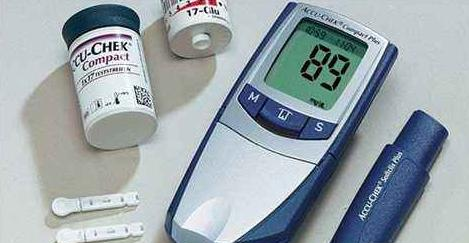
血糖仪是用于检测血液中葡萄糖近似浓度的设备,需要配合血糖试纸使用。血糖仪必须具有易于携带和电池使用寿命长的特点,以便消费者每天都需要测量多次的使用需求。本方案血糖仪的测试结果可以通过LCD显示,并且自动会记录和保存每次检测的时间与结果,通过USB或低功耗BLE将这些数据传输给PC和手机,方便医生或家人及时观察测试的结果。
优势
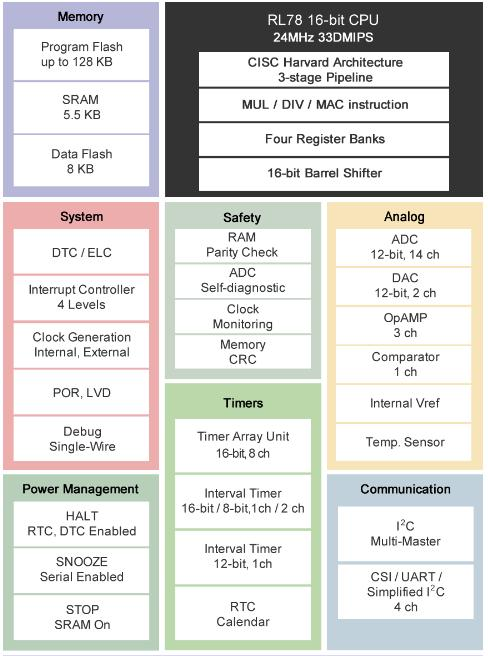
· 专为血糖仪应用开发的RL78/L1A系列MCU,集成了2个带多路复用开关的高精度轨到轨运算放大器、12位ADC、12位DAC、比较器以及LCD驱动器,简化了血糖仪的外围电路,减少产品的BOM成本。超低功耗的设计,工作电压低至1.8V,运行功耗66uA/MHz,休眠模式(RTC工作)时电流低于1uA,延长产品的电池寿命。
【RL78/L1A】
Low power 16-bit LCD microcontroller with rich analog integration.
The ultra low power RL78/L1A microcontroller family with embedded LCD has enhanced analog peripherals such as 12bit A/D converters, 12bit D/A converters, comparators, high accurate rail to rail OPAMPs with switch fabrics and comes with memory up to 128Kbyte Flash.
Using the smart features like DTC and ELC a lot of peripherals can be connected internally to reduce CPU workload and can save overall power consumption.
Available in 80pin and 100pin LFQFP packages this MCU line has been developed especially for healthcare Bio-sensing applications such as blood glucose meter, but is suitable for many other appliances which needs low power with LCD and rich analog peripherals.
Key Features:
| ITEM | RL78/L1A | ||
|---|---|---|---|
| Pin Count | 80pin | 100pin | |
| Part Name | R5F11MMx (X = D, E, F) | R5F11MPx (X = E,F,G) | |
Program Flash | 48 KB/64 KB/96 KB | 64 KB/96 KB/128 KB | |
Data Flash memory | 8 KB | 8 KB | |
SRAM | 5.5 KB | ||
Main System Clock | High Speed System Clock | 1 to 20MHz : Vdd = 2.7 to 3.6V 1 to 8MHz : Vdd = 1.8V to 2.7V | |
High speed On-chip Oscillator | HS mode : 1 to 24 MHz (Vdd = 2.7V to 3.6V) HS mode : 1 to 16 MHz (Vdd = 2.4V to 3.6V) LS mode : 1 to 8 MHz (Vdd = 1.8 to 3.6V) | ||
Sub System Clock | 32.768 kHz (TYP) : Vdd = 1.8 to 3.6V | ||
Low Speed On-chip Oscillator | 15 kHz (TYP) : Vdd = 1.8 to 3.6V | ||
I/O port | 59 | 79 | |
Timers | 16bit Timer TAU | 8 channels (Timer output x 8, PWM output x 7) | |
12bit Interval Timer | 1 channel (low power timer, usable also in STOP, HALT mode) | ||
8/16-bit interval timer | 2 channels (8 bit)/1 channels (16 bit) (cascadable low power timer, usable also in STOP, HALT mode to create long sleep intervals | ||
Real time clock (RTC) | 1 channel (calendar for 99 years, alarm function, and clock correction function) | ||
Real Time Clock Out | 1 channel, 1Hz (Sub System Clock : fsub = 32.768kHz) | ||
17bit Watch Dog Timer | 1 channel | ||
Clock output / Buzzer output | 2 channels | ||
12bit A/D converter | 10 channels | 14 channels | |
12bit D/A converter | 2 channels | 2 channels | |
Operation Amplifier | Rail to Rail OpAMP w/ MUX | 2 channels x 2 MUX | 2 channels x 4 MUX |
General Purpose | 1 channel | 1 channel | |
Comparator | 1 channel | 1 channel | |
Serial Communication Interface | CSI (SPI) : 1 channel / UART : 1 channel / Simple I2C : 1 channel CSI : 1 channel / UART : 1 channel / Simple I2C : 1 channel CSI : 1 channel / UART : 1 channel / Simple I2C : 1 channel CSI : 1 channel / UART : 1 channel / Simple I2C : 1 channel | ||
I2C bus | 1 channel | ||
LCD controller | Segment | 32 (28) | 45 (41) |
Common | 4 (8) | ||
Data Transfer Controller | 30 sources | ||
Event Link Controller | Event : 22, Event trigger: 8 | ||
Key Interrupt | 8 | ||
| Power On Reset | Power on reset : 1.51V +/- 0.04V Power down reset : 1.50 +/- 0.04V | ||
| Low Voltage Detector | Rising : 1.88V to 3.13V Falling : 1.84V to 3.06V | ||
| On-chip debugging | Yes | ||
| Power Supply Voltage | Vdd = 1.8V to 3.6V | ||
| Operation Temperature Range | Ta = -40℃ to +85℃ | ||
Pin Count / Memory Size Lineup:
Program Flash
SRAM
| 128KB 5.5KB | ● | |
|---|---|---|
| 96KB 5.5KB | ● | ● |
| 64KB 5.5KB | ● | ● |
| 48KB 5.5KB | ● | |
| Pins Package | 80 LFQFP | 100 LFQFP |
Block Diagram:
· 蓝牙SOC芯片(EFR32BG系列),集成低功耗的MCU和蓝牙射频,EM2模式电流仅1.5uA,节省产品能耗,还提供完整的开发套件和开发软件,工程师可以快速上手,缩短开发周期。
【EFR32BG】
EFR32BG 2.4 GHz 10.5 dBm Radio Board BRD4100A Reference Manual
The EFR32BG family of Wireless SoCs deliver a high performance,low energy wireless solution integrated into a small form factor package.
By combining a high performance 2.4 GHz RF transceiver with an energy efficient 32-bitMCU, the family provides designers the ultimate in flexibility with a family of pin-compatibledevices that scale from 128/256 kB of flash and 16/32 kB of RAM. The ultra-lowpower operating modes and fast wake-up times of the Silicon Labs energy friendly 32-bit MCUs, combined with the low transmit and receive power consumption of the 2.4 GHz radio, result in a solution optimized for battery powered applications.
To develop and/or evaluate the EFR32 Blue Gecko, the EFR32BG Radio Board can beconnected to the Wireless Starter Kit Mainboard to get access to display, buttons andadditional features from Expansion Boards.

RADIO BOARD FEATURES
• Wireless SoC:EFR32BG1P232F256GM48
• CPU core: ARM Cortex-M4 with FPU
• Flash memory: 256 kB
• RAM: 32 kB
• Operation frequency: 2.4 GHz
• Transmit power: 10.5 dBm
• Integrated PCB antenna, UFL connector(optional).
• Crystals for LFXO and HFXO: 32.768 kHz and 38.4 MHz.
1. Introduction
The EFR32 Blue Gecko Radio Boards provide a development platform (together with the Wireless Starter Kit Mainboard) for the SiliconLabs EFR32 Blue Gecko Wireless System on Chips and serve as reference designs for the matching network of the RF interface.
The BRD4100A Radio Board is designed to operate in the 2400-2483.5 MHz band with the RF matching network optimized to operatewith 10.5 dBm output power.
To develop and/or evaluate the EFR32 Blue Gecko, the BRD4100A Radio Board can be connected to the Wireless Starter Kit Mainboard to get access to display, buttons and additional features from Expansion Boards and also to evaluate the performance of the RFinterface.
2. Radio Board Connector
2.1 Introduction
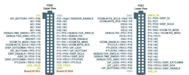
The board-to-board connector scheme allows access to all EFR32BG1 GPIO pins as well as the RESETn signal. For more information on the functions of the available pin functions, see the EFR32BG1 data sheet.
2.2 Radio Board Connector Pin Associations
The figure below shows the pin mapping on the connector to the radio pins and their function on the Wireless Starter Kit Mainboard.
3. Radio Board Block Summary
3.1 Introduction
This section gives a short introduction to the blocks of the BRD4100A Radio Board.
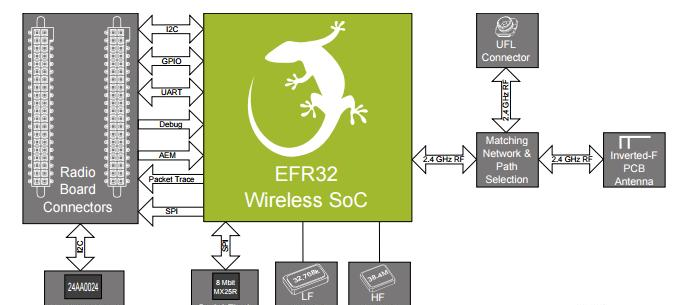
3.2 Radio Board Block Diagram
The block diagram of the EFR32BG Radio Board is shown in the figure below.
3.3 Radio Board Block Description
3.3.1 Wireless MCU
The BRD4100A EFR32 Blue Gecko Radio Board incorporates an EFR32BG1P232F256GM48 Wireless System on Chip featuring 32-bitCortex-M4 with FPU core, 256 kB of flash memory and 32 kB of RAM and a 2.4 GHz band transceiver with output power up to 10.5dBm. For additional information on the EFR32BG1P232F256GM48, refer to the EFR32BG1 Data Sheet.
3.3.2 LF Crystal Oscillator (LFXO)
The BRD4100A Radio Board has a 32.768 kHz crystal mounted.
3.3.3 HF Crystal Oscillator (HFXO)
The BRD4100A Radio Board has a 38.4 MHz crystal mounted.
3.3.4 Matching Network for 2.4 GHz
The BRD4100A Radio Board incorporates a 2.4 GHz matching network which connects the 2.4 GHz TRX pin of the EFR32BG1 to theone on-board printed Inverted-F antenna. The component values were optimized for the 2.4 GHz band RF performace and current consumptionwith 10.5 dBm output power.For detailed description of the matching network, see Chapter 4.2.1 Description of the 2.4 GHz RF Matching.
3.3.5 Inverted-F Antenna
The BRD4100A Radio Board includes a printed Inverted-F antenna (IFA) tuned to have close to 50 Ohm impedance at the 2.4 GHz
band.
For detailed description of the antenna see Chapter 4.5 Inverted-F Antenna.
3.3.6 UFL Connector
To be able to perform conducted measurements, Silicon Labs added an UFL connector to the Radio Board. The connector allows an external 50 Ohm cable or antenna to be connected during design verification or testing.
Note: By default the output of the matching network is connected to the printed Inverted-F antenna by a series component. It can be connected to the UFL connector as well through a series 0 Ohm resistor which is not mounted by default. For conducted measurements through the UFL connector the series component to the antenna should be removed and the 0 Ohm resistor should be mounted (see Chapter 4.2 Schematic of the RF Matching Network for further details).
3.3.7 Radio Board Connectors
Two dual-row, 0.05” pitch polarized connectors make up the EFR32BG Radio
Board interface to the Wireless Starter Kit Mainboard. For more information on
the pin mapping between the EFR32BG1P232F256GM48 and the Radio Board Connector,
refer to Chapter 2.2 Radio Board Connector Pin Associations.
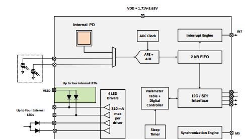
· 小于50uA运行功耗心率传感器(Si1175),增加产品续航时间,集成AFE、集成高灵敏度PhotoDiode、四颗LED;超过100db动态范围的AFE前端及24bit ADC,使心率测量更加准确,更预留外部PhotoDiode接口及加速度计同步接口,设计更加灵活,官方提供业界先进动态心率算法库,缩短开发周期。
【Si1175】
Si1175 Data Short
Optical Heart Rate Sensor Module
The module includes an IC with integrated photodetector and current-to-digital converter and LED drivers, along with multiple LEDs. It also supports external LEDs and Photodiodes.
This optical heart rate sensor module includes I2C and SPI digital interfaces, a programmable-event interrupt output, an analog-to-digital converter, host communications processor, four integrated LED drivers and inputs for two external photodiodes A large internal photodiode and high-efficiency LEDs combined with the two optical ports at different distances to the sensor create a high quality signal with different skin types.
The Si1175 offers excellent performance under a wide dynamic range. The Si1175 is provided in a 28 pin LGA Module and is capable of operation from 1.71 to 3.63 V over the –40 to +85 °C temperature range.
Sample Applications
• Fitness wearables
• Smart watches
• Other wearable devices that require low power heart rate monitoring
KEY FEATURES
• Low power, high dynamic range sensor optimized for wrist-based PPG sensing
• High performance motion compensated HR algorithm running on external MCU device
• Supports integration times from 9 μs to multiple seconds
• Average sensor current < 50 μA
• 24 bit ADC with over 100 dB dynamic range and built in averaging
• 2 kB FIFO interface
• 1.0 mm2 Internal PD
• Support for external photodiodes
• Support for up to 4 LEDs in the module
• Low sleep current: 500 nA
• Low power consumption: Flexible duty cycle optimizes power consumption
• Short delay between samples improves ambient light rejection
• Four LED drivers,independently programmable from 1.7 to 310 mA
• I2C host communications with Interrupts
• SPI host communications with interrupts
• Supports synchronization with an accelerometer
• 3.7 mm × 7.0 mm × 1.1 mm LGA module
• Rated for operation from –40 to 85 °C
相关元件供应:
型号:Q13MC1461000600 品牌:EPSON
型号:Q13MC1462000200 品牌:EPSON
型号:Q13FC1350004900 品牌:EPSON
型号:Q13MC1462000100 品牌:EPSON
型号:X1A000061000200 品牌:EPSON
型号:Q13FC1350000400 品牌:EPSON
【血糖仪】
血糖仪又称血糖计,是一种测量血糖水平的电子仪器。血糖仪从工作原理上分为光电型和电极型两种。电极型血糖仪的测试原理更科学,电极可内藏。
血糖仪从工作原理上有两种分别,一是光电型,一是电极型。光电血糖仪类似CD机,有一个光电头,它的优点是价格比较便宜,缺点是探测头暴露在空气里,很容易受到污染,影响测试结果,误差范围在正负0.8左右,使用寿命比较短, 一般在两年之内是比较准确的,两年后建议正在使用光电型机器的患者到维修站做一次校准。。一般医院有医院代表定期进行保养,而家用血糖仪则要到售后服务部进行光头保养。
电极型的测试原理更科学,电极口内藏,可以避免污染,误差范围一般在正负0.5左右。精度高,正常使用的情况下,不需要校准,寿命长。
血糖仪从采血方式上有两种,一是抹血式,一是吸血式。抹血的机器一般采血量比较大,患者比较痛苦。如果采血偏多,还会影响测试结果,血量不足,操作就会失败,浪费试纸,这种血糖仪多为光电式的。吸血式的血糖仪,试纸自己控制血样计量,不会因为血量的问题出现结果偏差,操作方便,用试纸点一下血滴就可以了。
现在多数血糖仪都是破损型的,就是需要采血,对于需要多次测量血糖的患者,有无破损血糖仪问世,但是价格非常高!为了减轻患者指尖采血的痛苦,现在推出两款手臂采血的血糖仪。
糖测量通常采用电化学分析中的三电极体系。三电极体系是相对于传统的两电极体系而言,包括,工作电极(WE),参比电极(RE)和对电极 (CE)。参比电极用来定点位零点,电流流经工作电极和参比电极构成一个不通或基本少通电的体系,利用参比电极电位的稳定性来测量工作电极的电极电势。工作电极和辅助电极构成一个通电的体系,用来测量工作电极通过的电流。利用三电极测量体系,来同时研究工作电极的点位和电流的关系。
作为一个糖尿病患者,监控血糖了解体内血糖变化,可以影响到我们的整个治疗,误差在多少是可以接受的,往往成了关注焦点。世界卫生组织及美国食品药品监督管理局的多项数据表明,血糖仪的测试误差在20%以内,均不会影响到患者的治疗方案,例:连续3次测定血糖,分别为6.4mmol/l、5.5mmol/l5.9mmol/l。虽然数字不尽相同,但可以看出血糖控制良好,因而不必改动治疗方案。
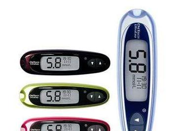
这是所有血糖仪共有的一种特性,不是某一品牌、某一款血糖仪的问题。患者自测血糖时常遇到不同品牌或相同品牌血糖仪之间测量结果不一致的问题,其实这些都是很正常的,因为快速血糖仪测量的结果是范围值,每次测量的结果通常会有一些差异,但差异不会太大,快速血糖仪同生化仪静脉血糖之间的误差不超过20%都是准确的,有些患者对仪器测量的数据理解存在问题,认为血糖仪的测量数据应该和通过静脉测量的血糖值是一样的,如果这两个数值出现不一样的情况,产品质量就有问题。但事实上,不论是家用的血糖仪还是医院的测血糖仪器,测出的数值不会每次都一样,应该说误差值在±10%以内的血糖仪就是非常好的,一般要求误差不超过±20%,在这个问题上没有绝对正确,只有相对正确。当然,测量中的一些错误方法也会人为的影响结果的准确性。
责任编辑:Davia
【免责声明】
1、本文内容、数据、图表等来源于网络引用或其他公开资料,版权归属原作者、原发表出处。若版权所有方对本文的引用持有异议,请联系拍明芯城(marketing@iczoom.com),本方将及时处理。
2、本文的引用仅供读者交流学习使用,不涉及商业目的。
3、本文内容仅代表作者观点,拍明芯城不对内容的准确性、可靠性或完整性提供明示或暗示的保证。读者阅读本文后做出的决定或行为,是基于自主意愿和独立判断做出的,请读者明确相关结果。
4、如需转载本方拥有版权的文章,请联系拍明芯城(marketing@iczoom.com)注明“转载原因”。未经允许私自转载拍明芯城将保留追究其法律责任的权利。
拍明芯城拥有对此声明的最终解释权。


 产品分类
产品分类


 2012- 2022 拍明芯城ICZOOM.com 版权所有 客服热线:400-693-8369 (9:00-18:00)


