基于Infineon公司的ICL5101110W-54V LED驱动解决方案
 107
107
 拍明
拍明
原标题:Infineon ICL5101110W-54V LED驱动解决方案
infineon公司的ICL5101是用于LED驱动器的高压谐振控制器,PFC级工作在CrCM和DCM模式,支持低负载工作条件.器件集成了高边和低边驱动器,从而降低了外接元件数量,具有小于200ms的超快点亮时间,PFC大于99%,THD小于5%,而效率高达94%.本文介绍了ICL5101产品亮点和主要特性,应用电路图,以及110W/54V LED驱动器演示板主要特性,电路图,材料清单和PCB设计文件图.
The LED Resonant controller ICL5101is designed to control resonant convertertopologies. The PFC stage operates in CrCM andDCM mode, supporting low load conditions.
Integrated high and low side drivers assure a lowcount of external components, enabling small formfactor designs.
ICL5101 parameters are adjusted by simpleresistors only, this being the ideal choice to easethe design-in process. A comprehensive set ofprotection features ensures that the LED driverdetects fault conditions, protecting both the LEDdriver and the LED load.
ICL5101产品亮点:
Supports universal input and wide output range
Low count of external components supportingsmall form factors and improved reliability
All parameters set by simple resistors only
Supports outdoor use by extended junctiontemperature range from -40 ℃ to +125 ℃
Stable low load operation mode down to 0.1 %of nominal power rating
Comprehensive set of protection features incl.external over temperature protection and
capacitive load protection to increase systemsafety
Ultra-fast time to light < 200 ms
Power Factor Correction > 99 %,THD < 5 %
High efficiency up to 94 %
PFC feature set
PFC in CritCM mode during nominal load andDCM mode in low load condition down to 0.1 %
for operation without audible noise
Improved compensation for low THD of ACinput current even in DCM operation
Adjustable PFC current limitation
Resonant half bridge feature set
Fully integrated 650 V high-side driver
Self-adaptive dead time control of the integratedhalf bridge driver 500 ns – 1.0 μs
Detection of capacitive operation, overload,short circuitry and output overvoltage
Improved operation control in magneticsaturation during start-up
Advanced error detection control
This application note describes the characteristics and features of a 110 W SMPS demonstration board withconstant 54 V voltage output. High efficiency, high PF, low iATHD and very stable output voltage with lowripple at whole power range are the key features of this demonstration board, which makes it very suitableto be used as a primary power supply for low power systems, such as LED lighting. Its compact design andlow BOM cost is due to Infineon IC ICL5101 (CritCM PFC and resonant block are integrated together), which isused as main controller here. With this highly integrated smart IC, the circuit design is dramaticallysimplified, which results space and BOM cost saving. Furthermore, numerous monitor and protectionfeatures ensure highest reliability.
This demo board consists of a CrCM PFC and a half-bridge LLC, which outputs a stable 54 VDC voltage.The PFC stage of this demo board is controlled by the PFC block of the ICL5105, which has an integrateddigital PFC control loop and improved compensation for low THD of AC input current. It operates in criticalconductionmode (CrCM) in a load range from10%to 100%to achieve a very good power factor and verylow THD. When the load is smaller than 10%, in order to limit the PFC switching frequency, the IC controlsthe PFC to operate in discontinuous conductionmode (DCM).
The half-bridge LLC stage has a fixed duty cycle of D=0.5 and an adjustable self-adapting dead time from0.5 μs to 1 μs. The operation frequency starts fromtypical 135 kHz at start-up and decreases to a range ofbetween 45 kHz (full load) and 75 kHz (output open loop). The 54 V output voltage has a very stable valuethroughout the whole output power range. The value variation is tested to be smaller than 0.2%fromfullload to open loop. Over voltage protection (OVP) is implemented at themain output. When the outputvoltage reaches 60 V, themain converter is stopped by the OVP circuit. It starts to operate again when themain output decreases to 54 V. In addition,many other protection functions are also implemented, such as Output Short Circuit Protection of themain output (OSCP), LLC primary winding short circuit protection(WSCP), Capacitive Mode Protection of themain output (CMP), LLC Over Current Protection (LOCP), overtemperature protection (OTP) at certain hot spot on board andmore. These protection functions arerealized by the built-in protection functions of the IC ICL5105.
110W/54V LED驱动器演示板主要特性:
Input voltage range: 85–305 VAC
Input voltage frequency: 47–63 Hz
Regulatedmain output voltage: 54 VDC / 2.06 A
Efficiency at nominal load: ≥ 93.5 % at 230 VAC
Input current THD: <10%@> 35%Load at 230 VAC
Harmonics: According to EN61000-3-2 Class-D
EMI: According to EN55015
Safety : According to EN61347-2-13
Board dimensions: 247.3mm(L) x 48.25mm(W) x 34.2mm(H)
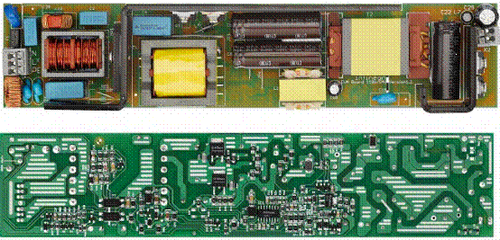
图.110W/54V LED驱动器演示板外形图
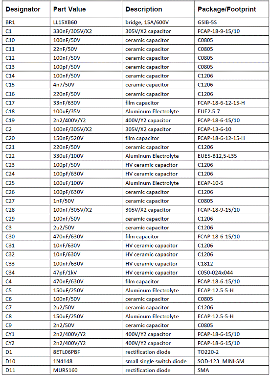
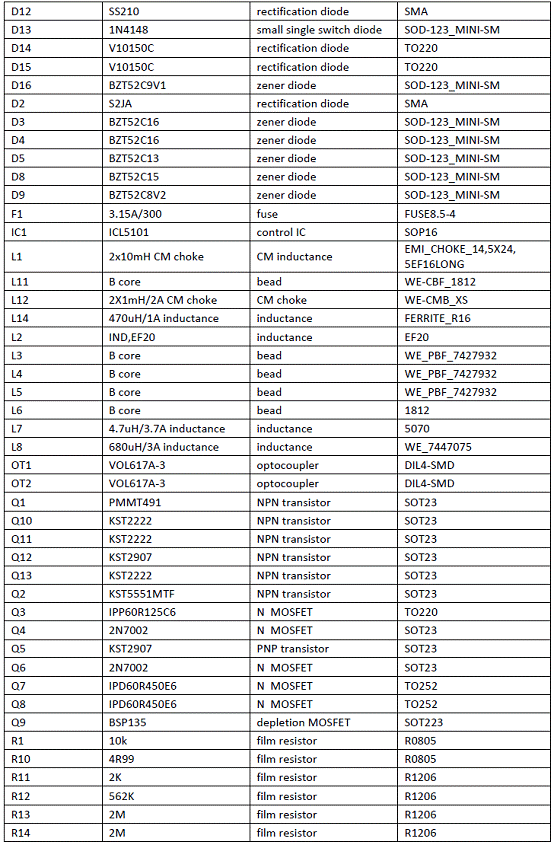
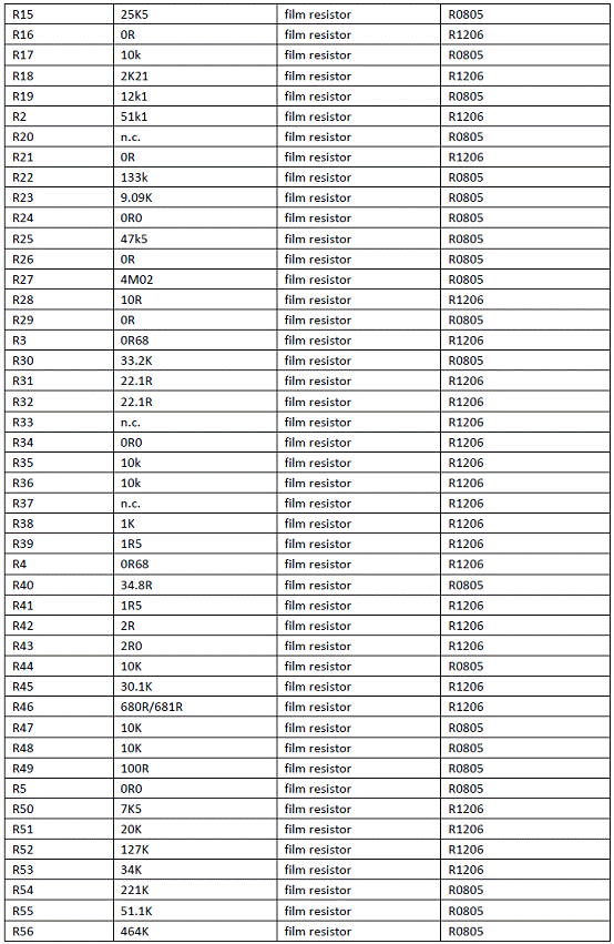
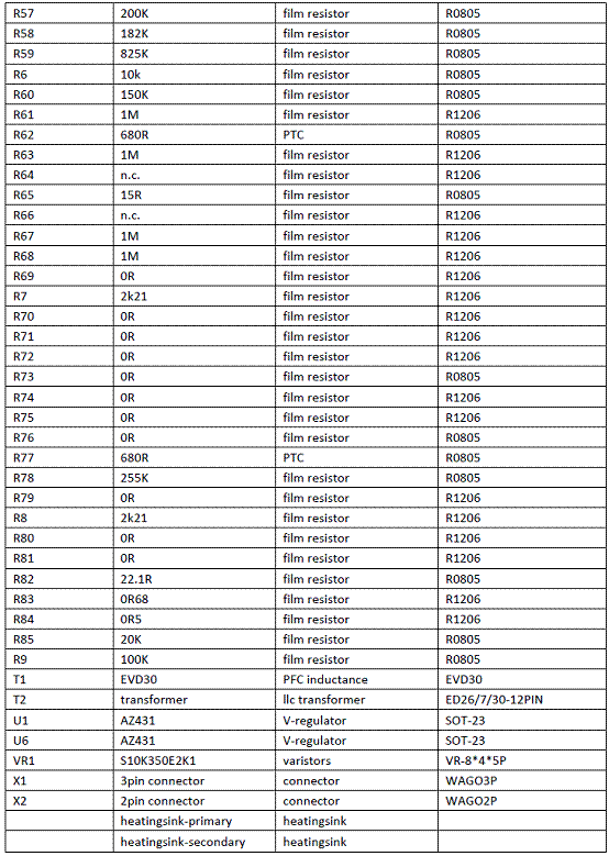
110W/54V LED驱动器演示板材料清单:
责任编辑:HanFeng
【免责声明】
1、本文内容、数据、图表等来源于网络引用或其他公开资料,版权归属原作者、原发表出处。若版权所有方对本文的引用持有异议,请联系拍明芯城(marketing@iczoom.com),本方将及时处理。
2、本文的引用仅供读者交流学习使用,不涉及商业目的。
3、本文内容仅代表作者观点,拍明芯城不对内容的准确性、可靠性或完整性提供明示或暗示的保证。读者阅读本文后做出的决定或行为,是基于自主意愿和独立判断做出的,请读者明确相关结果。
4、如需转载本方拥有版权的文章,请联系拍明芯城(marketing@iczoom.com)注明“转载原因”。未经允许私自转载拍明芯城将保留追究其法律责任的权利。
拍明芯城拥有对此声明的最终解释权。


 产品分类
产品分类


 2012- 2022 拍明芯城ICZOOM.com 版权所有 客服热线:400-693-8369 (9:00-18:00)


