SiC MOSFET Drives Powertrain Inverter Performance
 14
14
 拍明
拍明
原标题:SiC MOSFET Drives Powertrain Inverter Performance
Component R&D activity continues to yield higher-performance devices, characterized by higher efficiency and better electrical characteristics. One focus is silicon-carbide (SiC) technology, which can achieve the same electrical resistance as silicon but with a smaller mass, thereby enabling smaller, more efficient power devices. Because switching losses are reduced with SiC, high-frequency operation is possible using smaller passive components. Moreover, SiC devices can operate at higher temperatures and thus enable a reduced thermal design footprint, making them ideal for use in automotive applications.
SiC usage provides other benefits as well. SiC power losses are up to 10 times lower than silicon’s. A tenfold increase in the electrical breakdown field (V/cm) relative to silicon enables higher-voltage operation. The cooling coefficient (thermal conductivity measured in W/cm × °C) of SiC is triple that of silicon, and SiC yields a factor-of-10 improvement in frequency response.
Those outstanding electrical and physical characteristics have made silicon carbide the dominant power device technology for use in automotive applications, which can benefit from smaller devices, including smaller passive components, and simpler cooling schemes. In the past few years, the number of car companies building SiC-based inverter prototypes has dramatically increased. Today, 80% of automotive drivetrain activity involves SiC in some way, and the remaining 20% will likely follow suit. This is despite the higher costs and more complex fabrication processes for SiC devices.
The primary automotive applications for SiC power MOSFETs, diodes, and modules are on-board electric vehicle (EV) chargers, DC/DC converters, and drivetrain inverters. Plug-in hybrid EVs and battery EVs (BEVs) use on-board chargers to “refuel” the vehicle battery either at home or at a public charging station. The principle of operation is quite simple: The charger takes socket power of 90 to 265 VAC and converts it to DC to charge the battery. Drivetrain devices are used in BEV powertrain and commercial vehicles. The drivetrain is a significant and challenging application. As a result, it presents a tremendous opportunity for innovation.
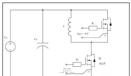
Figure 1: Clamped inductive switching test circuit for E-Series automotive SiC power MOSFET (Image: Wolfspeed)
The SiC MOSFETs in Wolfspeed’s E-Series line offer the industry’s lowest switching losses and highest figure of merit, according to the company. E-Series MOSFETs (Figure 1) are optimized for use in EV battery chargers and high-voltage DC/DC converters and are featured in Wolfspeed’s reference design for a 6.6-kW bidirectional on-board charger.
EV OPERATION
Figure 2 presents a block diagram illustrating the basic operation of an electric vehicle. We can see the blocks related to the main functionalities, such as the on-board charger (which allows connection to an external AC charging station), wireless charger,
DC/DC converter, high-power DC/DC converter (which allows connection to a DC fast-charging station), and inverter — the main subject of this article.
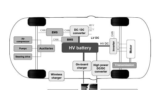
Figure 2: Basic EV operation. EMS stands for energy management system and BMS for battery management system. (Image: EE Times Europe)
A priority for EV developers is maximizing the distance a vehicle can travel on a battery charge. In 2012–2013, EVs could guarantee a range of about 140 km using the performant accumulators available at the time. Today, battery capacity has greatly increased, allowing a travel distance of 400 km or more between charges. That is indeed a great result, comparable to what can be obtained with a petrol-fueled engine. Nevertheless, longer- distance capability requires a larger battery, which, in turn, requires a longer charging time and vehicle wiring that can support the necessary increase in power levels.
Existing charging stations can provide high power levels, of roughly 350 kWh or more, and thus are already equipped to support charging requirements for the immediate future. On the vehicle side, SiC is widely used to deliver the required higher efficiency and high-power capabilities. Figure 3 presents the schematics for a very common EV charger, capable of delivering low power of between 3.6 and 7.2 kWh.
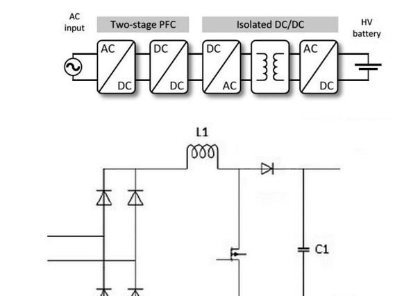
Figure 3: A typical charger circuit (Image: EE Times Europe)
The circuit layout is based on a two-stage power-factor correction (PFC) circuit and an isolated DC/DC converter that powers the high-voltage battery. For improved PFC operation, the booster diode is typically based on SiC technology. In the schematics, the booster diode is a standard component and not an add-on solution, as one might erroneously assume. SiC diodes allow higher switching frequencies than silicon-based equivalents. The waveforms recorded during several tests performed on SiC diodes from ROHM Semiconductor were found to be excellent, and the reverse-recovery time was quite low compared with the results achieved using a standard 650-V fast silicon diode. The SiC diode’s temperature dependence is practically nonexistent, making it an ideal solution for the most demanding applications.
FORMULA E INVERTER
In auto racing, the fitness of the vehicle has always mattered as much as the skill of the driver, and even a small technical tweak to the car can mean a better result at the finish line. This is true not just for conventional racecars but for Formula E cars as well. The availability of SiC 1,200-V inverters is enabling smaller and lighter automotive systems. Engine torque is also positively affected, benefiting Formula E vehicle design.
Replacing an insulated gate bipolar transistor (IGBT)-based inverter with a SiC-based inverter can increase power by 10%. The maximum change in switching frequency is 24 kHz with SiC, versus 16 kHz for the IGBT equivalent. The overall weight of the solution is reduced from 15 kg to 9 kg, and the overall volume drops from 14 liters to 10 liters (a 30% reduction). Tests performed by ROHM Semiconductor indicate that available power is increased. For a Formula E car, this translates to rapid acceleration, helping the car reach top speed off the starting line ahead of the competition and cross the finish line with the top finishers.
But the battery must also be considered, as it dictates the amount of available energy. A SiC MOSFET simulation conducted by ROHM Semiconductor sheds light on the technology’s main advantages. The standard profile used for the simulation, Class 3B WLTP, measures speed, number of revolutions (RPM), and torque. The simulation references a 100-kWh engine, a 16-kHz switching frequency, and a 750-V/33-kWh battery. Two power modules are compared: the BSM600D12 SiC 12,000-V/600-A module and the SKIM459GD12E4 IGBT module.
ROHM ran several simulations and analyzed the results. It found that a distance of 177 km was traveled using the SiC power module (Figure 4), up from the 159 km obtained with the IGBT version. It therefore concludes that merely changing the fabrication technology can result in an immediate and tangible benefit to the customer, who can design a system that can either enable a longer driving distance between charges with a battery of the same size or allow the use of a smaller battery, at a lower overall cost, without compromising performance (travel distance between charges) for the end customer — the driver.
Looking to the future, we expect a significant increase in power density. In other words, all efforts are being focused on obtaining the highest possible amount of energy from the smallest plausible footprint. Therefore, higher-power engines will be built with smaller components, lowering the price per kWh.
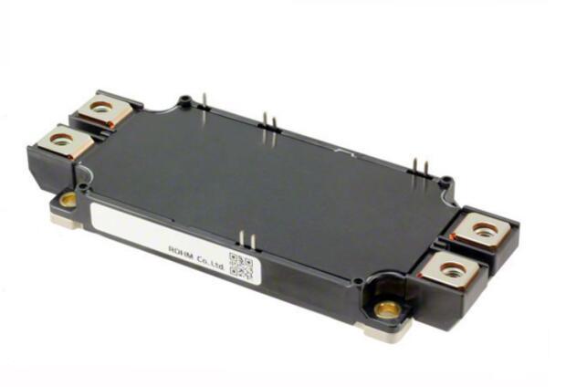
Figure 4: The BSM600D12 SiC-based 12,000-V/600-A module (Image: ROHM Semiconductor)
Silicon carbide remains more costly than most alternatives. SiC power devices require more complex, and thus more expensive, fabrication steps than conventional, silicon-based devices. Ultimately, however, SiC’s power-density benefits will shift the cost/performance equation in its favor. SiC will find even broader adoption in automotive applications, DC/DC charging circuits, and power converters. SiC inverters will continue to displace silicon-based IGBT inverters as more developers look to leverage silicon carbide’s efficiency and power-density benefits. ■
责任编辑:David
【免责声明】
1、本文内容、数据、图表等来源于网络引用或其他公开资料,版权归属原作者、原发表出处。若版权所有方对本文的引用持有异议,请联系拍明芯城(marketing@iczoom.com),本方将及时处理。
2、本文的引用仅供读者交流学习使用,不涉及商业目的。
3、本文内容仅代表作者观点,拍明芯城不对内容的准确性、可靠性或完整性提供明示或暗示的保证。读者阅读本文后做出的决定或行为,是基于自主意愿和独立判断做出的,请读者明确相关结果。
4、如需转载本方拥有版权的文章,请联系拍明芯城(marketing@iczoom.com)注明“转载原因”。未经允许私自转载拍明芯城将保留追究其法律责任的权利。
拍明芯城拥有对此声明的最终解释权。


 产品分类
产品分类




 2012- 2022 拍明芯城ICZOOM.com 版权所有 客服热线:400-693-8369 (9:00-18:00)


