基于Microchip PIC18F87J72微控制器的单相电表参考设计方案
 31
31
 拍明
拍明
原标题:基于Microchip PIC18F87J72单相电表参考设计方案
Microchip公司的PIC18F87J72是集成了双路24位AFE,LCD驱动器的高性能微控制器,具有nanoWatt技术,每路的模拟特性包括90 dB SINAD, -101 dBc THD (到35次谐波)以及103 dB SFDR,和10ppm INL,差分输入引脚,可编程数据速率到64ksps,高增益PGA到32V/V,基准电压源低漂移(12ppm/度C),主要用在低成本电表,电源测量和监视,手持仪表和医疗监视。本文介绍了PIC18F87J72主要特性,功能框图,单相电表应用电路图以及PIC18F87J72单相电表参考设计主要特性,电路图,材料清单和PCB布局图。
This family combines the traditional advantages of all PIC18 microcontrollers – namely, high computational performance and a rich feature set – with a versatile on-chip LCD driver and a high-performance, high-accuracy analog front end. These features make the PIC18F87J72 family a logical choice for many high-performance power and metering applications where price is a primary consideration.
PIC18F87J72主要特性:
Analog Features:
? Dual-Channel, 24-Bit Analog Front End (AFE):
- 90 dB SINAD, -101 dBc THD (to 35th harmonic),103 dB SFDR for each channel
- 10 ppm INL
- Differential voltage input pins
- Low drift internal voltage reference (12 ppm/C)
- Programmable data rate to 64 ksps
- High-gain PGA on each channel (up to 32 V/V)
- Phase delay compensation between channels (1 ?s resolution)
12-Bit, 12-Channel SAR A/D Converter:
- Auto-acquisition
- Conversion available during Sleep
? Two Analog Comparators
? Programmable Reference Voltage for Comparators
? Charge Time Measurement Unit (CTMU):
- Capacitance measurement
- Time measurement with 1 ns typical resolution
- Temperature sensing
LCD Driver and Keypad Interface
Features:
? Direct LCD Panel Drive Capability:
- Can drive LCD panel while in Sleep mode
- Wake-up from interrupt
? Up to 33 Segments and 132 Pixels: Software Selectable
? Programmable LCD Timing module:
- Multiple LCD timing sources available
- Up to four commons: static, 1/2, 1/3 or
1/4 multiplex
- Static, 1/2 or 1/3 bias configuration
? On-Chip LCD Boost Voltage Regulator for
Contrast Control
? CTMU for Capacitive Touch Sensing
? ADC for Resistive Touch Sensing
Flexible Oscillator Structure:
? External Crystal and Clock modes, with operation
up to 48 MHz
? 4x Phase Lock Loop (PLL)
? Internal Oscillator Block with PLL:
- Eight user-selectable frequencies from 31.25 kHz to 8 MHz
? Secondary Oscillator using Timer1 at 32 kHz
? Fail-Safe Clock Monitor (FSCM):
- Allows for safe shutdown if peripheral clock fails
Low-Power Features:
? Power-Managed modes:
- Run: CPU on, peripherals on
- Idle: CPU off, peripherals on
- Sleep: CPU off, peripherals off
? Two-Speed Oscillator Start-up
Peripheral Highlights:
? High-Current Sink/Source 25 mA/25 mA (PORTB and PORTC)
? Up to Four External Interrupts
? Four 8-Bit/16-Bit Timer/Counter modules
? Two Capture/Compare/PWM (CCP) modules
? Master Synchronous Serial Port (MSSP) module with
Two Modes of Operation:
- 3-wire/4-wire SPI (supports all four SPI modes)
- I2C. Master and Slave mode
? One Addressable USART module
? One Enhanced Addressable USART module:
- LIN/J2602 support
- Auto-wake-up on Start bit and Break character
- Auto-Baud Detect (ABD)
? Hardware Real-Time Clock and Calendar (RTCC) with
Clock, Calendar and Alarm Functions
Special Microcontroller Features:
? 10,000 Erase/Write Cycle Flash Program Memory, Typical
? Flash Retention 20 Years, Minimum
? Self-Programmable under Software Control
? Word Write Capability for Flash Program Memory for Data EEPROM Emulators
? Priority Levels for Interrupts
? 8 x 8 Single-Cycle Hardware Multiplier
? Extended Watchdog Timer (WDT):
- Programmable period from 4 ms to 131s
? Selectable Open-Drain Configuration for Serial Communication and CCP pins for Driving Outputs up to 5V
? In-Circuit Serial Programming. (ICSP.) via Two Pins
? In-Circuit Debug via Two Pins
? Operating Voltage Range: 4.5V to 5.5V (兇兠僴ADC), 2.0V to 3.6V (digital and SAR ADC)
? 5.5V Tolerant Input (digital pins only)
? On-Chip 2.5V Regulator
PIC18F87J72目标应用:
? Energy Metering
? Power Measurement and Monitoring
? Portable Instrumentation
? Medical Monitoring

图1.PIC18F87J72功能框图
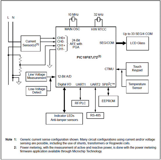
图2.PIC18F87J72单相电表应用电路图
PIC18F87J72单相电表参考设计
The PIC18F87J72 Single-Phase Energy Meter Reference Design is a fully functional single-phase meter based on the highly integrated PIC18F87J72 single-chip energy meter IC. This low-cost design does not use any transformers and requires few external components. The PIC18F87J72 directly drives the LCD, and includes both an isolated USB connection and a non-isolated RS-232 interface for meter calibration and access to the device power calculations. The system calculates active energy, active power, reactive energy, reactive power, RMS current, RMS voltage and other typical power quantities.
The Microchip Energy Meter 1-Phase Software is used to calibrate and monitor the system, and can be used to create custom calibration setups. For some accuracy requirements, only a single-point calibration may be needed. The energy meter software offers an automated step by step calibration process that can be used to quickly calibrate energy meters.
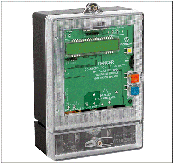
图3.PIC18F87J72单相电表外形图
PIC18F87J72单相电表参考设计主要特性:
• Working single phase energy meter
• Energy calculation firmware: Active/Reactive Energy; Forward/Reverse Energy; Active/Reactive/Apparent Power; RMS Current & Voltage; Editable by meter designer
• GUI-assisted software calibration
• LCD display for energy
• Low cost shunt based design
• Better than IEC Class 0.5 performance

图4.PIC18F87J72单相电表参考设计电路图
PIC18F87J72单相电表参考设计材料清单(BOM):
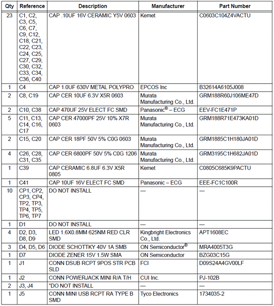
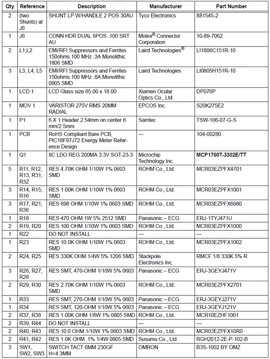
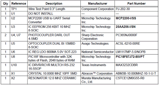
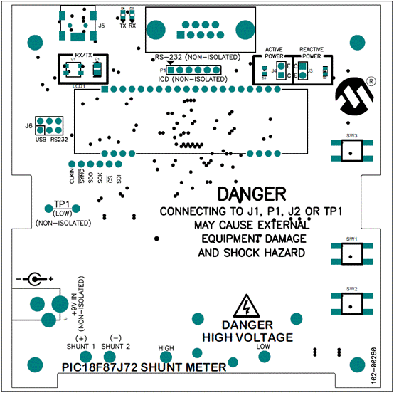
图5.PIC18F87J72单相电表PCB布局图(顶层)(1)
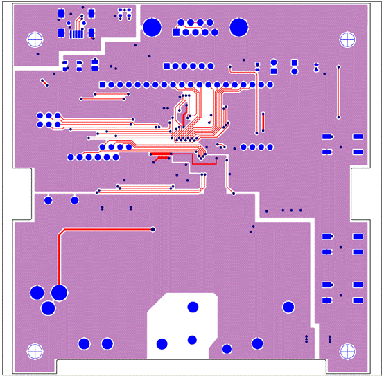
图5.PIC18F87J72单相电表PCB布局图(顶层)(2)
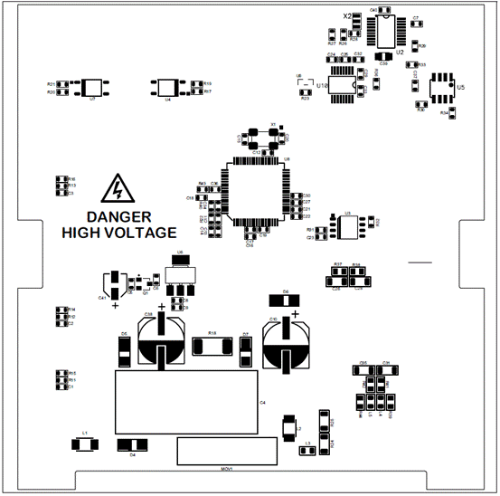
图7.PIC18F87J72单相电表PCB布局图(底层)(1)
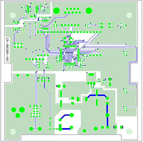
图8.PIC18F87J72单相电表PCB布局图(底层)(2)
详情请见:
![]() 39979A.pdf(4.4 MB)2012-8-23 13:41 上传
39979A.pdf(4.4 MB)2012-8-23 13:41 上传
-1
![]() 51931a.pdf(2.11 MB)2012-8-23 13:42 上传
51931a.pdf(2.11 MB)2012-8-23 13:42 上传
-1
以及
![]() 103-00280-R2.pdf(200.84 KB)2012-8-23 13:39 上传
103-00280-R2.pdf(200.84 KB)2012-8-23 13:39 上传
-1
责任编辑:David
【免责声明】
1、本文内容、数据、图表等来源于网络引用或其他公开资料,版权归属原作者、原发表出处。若版权所有方对本文的引用持有异议,请联系拍明芯城(marketing@iczoom.com),本方将及时处理。
2、本文的引用仅供读者交流学习使用,不涉及商业目的。
3、本文内容仅代表作者观点,拍明芯城不对内容的准确性、可靠性或完整性提供明示或暗示的保证。读者阅读本文后做出的决定或行为,是基于自主意愿和独立判断做出的,请读者明确相关结果。
4、如需转载本方拥有版权的文章,请联系拍明芯城(marketing@iczoom.com)注明“转载原因”。未经允许私自转载拍明芯城将保留追究其法律责任的权利。
拍明芯城拥有对此声明的最终解释权。


 产品分类
产品分类


 2012- 2022 拍明芯城ICZOOM.com 版权所有 客服热线:400-693-8369 (9:00-18:00)


