基于PowerInt InnoSwitch3-CE系列650V MOSFET 65W电源参考设计DER535解决方案
 815
815
 拍明
拍明
PowerInt公司的InnoSwitch3-CE系列是集成了650V MOSFET,同步整流和FluxLink反馈的离线CV/CC QR反激开关集成电路,具有多种保护如线路过压和欠压保护,输出过压和过流限制,超温关断等,满负载效率高达94%,无负载功耗小于15mW,绝缘电压>4000 VAC,主要用在高达65W的高效反激电源,移动设备的大电流充电器和适配器,以及消费类电子如机顶盒(STB),网络,游戏和LED.本文介绍了InnoSwitch3-CE系列产品亮点,初级和次级控制器框图,典型应用电路,以及采用InnoSwitch3-CE, INN3168C-H101的65W电源参考设计DER535主要特性和指标,电路图,材料清单和PCB设计图.
The InnoSwitch™3-CE family of ICs dramatically simplifies the designand manufacture of flyback power converters, particularly thoserequiring high efficiency and/or compact size. The InnoSwitch3-CEfamily incorporates primary and secondary controllers and safety-ratedfeedback into a single IC.
InnoSwitch3-CE family devices incorporate multiple protection featuresincluding line over and under-voltage protection, output over-voltageand over-current limiting, and over-temperature shutdown. Devices areavailable that support the common combinations of latching andauto-restart behaviors required by applications such as chargers,adapters, consumer electronics and industrial systems. The devices areavailable with and without cable-drop compensation.
InnoSwitch3-CE系列产品亮点:
Highly Integrated, Compact Footprint
• Up to 94% efficiency across full load range
• Incorporates a multi-mode Quasi-Resonant (QR) / CCM flybackcontroller, 650 V MOSFET, secondary-side sensing and synchronousrectification driver
• Integrated FluxLink™, HIPOT-isolated, feedback link
• Exceptional CV/CC accuracy, independent of external components
• Adjustable accurate output current sense using external sense resistor
EcoSmart™ – Energy Efficient
• Less than 15 mW no-load including line sense
• Easily meets all global energy efficiency regulations
• Low heat dissipation
Advanced Protection / Safety Features
• Secondary MOSFET or diode short-circuit protection
• Open SR FET-gate detection
• Fast input line UV/OV protection
Optional Features
• Cable-drop compensation with multiple settings
• Variable output voltage, constant current profiles
• Auto-restart or latching fault response for output OVP/UVP
• Multiple output UV fault thresholds
• Latching or hysteretic primary over-temperature protection
Full Safety and Regulatory Compliance
• Reinforced isolation
• Isolation voltage >4000 VAC
• 100% production HIPOT testing
• UL1577 and TUV (EN60950) safety approved
• Excellent noise immunity enables designs that achieve class “A”performance criteria for EN61000-4 suite; EN61000-4-2, 4-3 (30V/m), 4-4, 4-5, 4-6, 4-8 (100 A/m) and 4-9 (1000 A/m) and FordFMC1278 (RI-115)
Green Package
• Halogen free and RoHS compliant
InnoSwitch3-CE系列应用:
• High efficiency flyback designs up to 65 W
• High current charger and adaptors for mobile devices
• Consumer electronics − set-top boxes, networking, gaming, LED
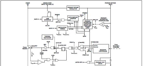
图1.InnoSwitch3-CE系列初级控制器框图
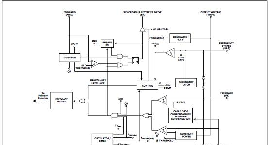
图2.InnoSwitch3-CE系列次级控制器框图
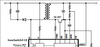
图3.InnoSwitch3-CE系列典型应用电路图
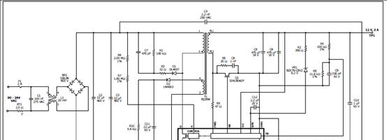
图4.InnoSwitch3-CE系列应用电路:12V/3A充电器/适配器
采用InnoSwitch3-CE, INN3168C-H101的65W电源参考设计DER535
This document is an engineering report describing a 19 V, 3.4 A power supply utilizingINN3168C from the InnoSwitch3-CH family of ICs.
This design shows the high power density and efficiency that is possible due to the high level of integration while still providing exceptional performance.
The document contains the power supply specification, schematic, bill of materials,transformer documentation, printed circuit layout, and performance data.
65W电源参考设计DER535主要特性:
Built in synchronous rectification for >90% efficiency without NTC at nominal AC input
All the benefits of secondary side control with the simplicity of primary side regulation
Insensitive to transformer variation
Extremely fast transient response independent of load timing
Secondary sensed output overvoltage protection (OVP) for accurate fault protection
Accurate thermal protection with hysteretic shutdown
Input voltage monitor with accurate brown-in/brown-out and overvoltage protection
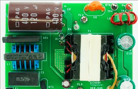
图5. 65W电源参考设计DER535外形图(正面)
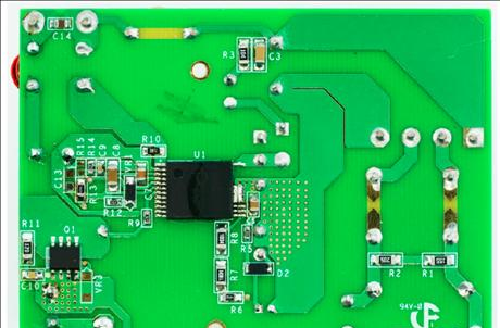
图6. 65W电源参考设计DER535外形图(背面)
65W电源参考设计DER535主要指标:
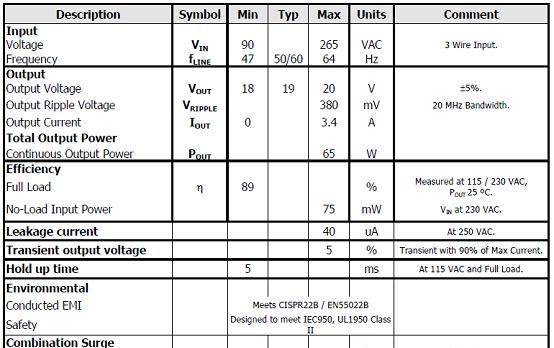
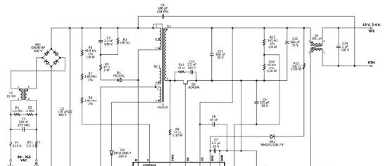
图7. 65W电源参考设计DER535电路图
65W电源参考设计DER53材料清单:
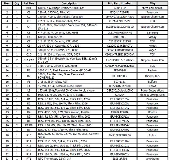
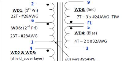
图8. 65W电源参考设计DER535变压器电路图
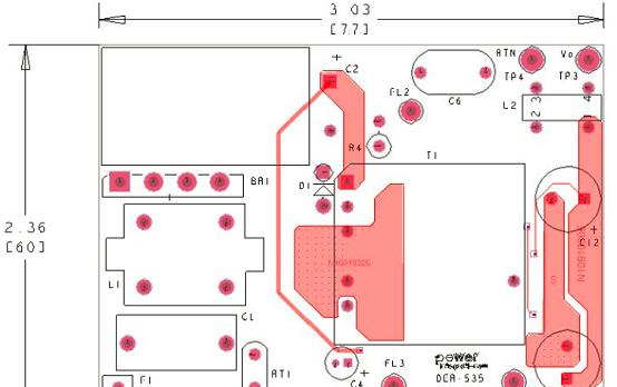
图9. 65W电源参考设计DER535 PCB设计图(正面)
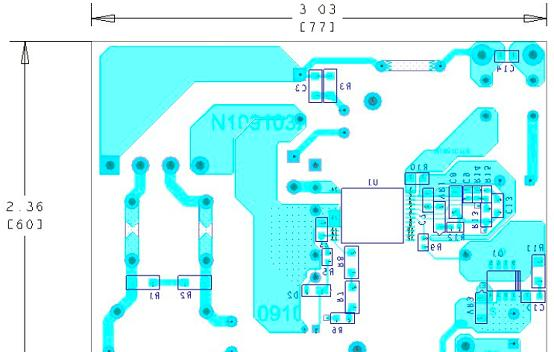
图10. 65W电源参考设计DER535 PCB设计图(背面)
![]() innoswitch3-ce_family_datasheet.pdf.pdf
innoswitch3-ce_family_datasheet.pdf.pdf
MOSFET
金属-氧化物半导体场效应晶体管,简称金氧半场效晶体管(Metal-Oxide-Semiconductor Field-Effect Transistor, MOSFET)是一种可以广泛使用在模拟电路与数字电路的场效晶体管(field-effect transistor)。MOSFET依照其“通道”(工作载流子)的极性不同,可分为“N型”与“P型” 的两种类型,通常又称为NMOSFET与PMOSFET,其他简称尚包括NMOS、PMOS等。
MOSFET工作原理
要使增强型N沟道MOSFET工作,要在G、S之间加正电压VGS及在D、S之间加正电压VDS,则产生正向工作电流ID。改变VGS的电压可控制工作电流ID。如图所示。
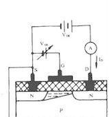
若先不接VGS(即VGS=0),在D与S极之间加一正电压VDS,漏极D与衬底之间的PN结处于反向,因此漏源之间不能导电。如果在栅极G与源极S之间加一电压VGS。此时可以将栅极与衬底看作电容器的两个极板,而氧化物绝缘层作为电容器的介质。当加上VGS时,在绝缘层和栅极界面上感应出正电荷,而在绝缘层和P型衬底界面上感应出负电荷。这层感应的负电荷和P型衬底中的多数载流子(空穴)的极性相反,所以称为“反型层”,这反型层有可能将漏与源的两N型区连接起来形成导电沟道。当VGS电压太低时,感应出来的负电荷较少,它将被P型衬底中的空穴中和,因此在这种情况时,漏源之间仍然无电流ID。当VGS增加到一定值时,其感应的负电荷把两个分离的N区沟通形成N沟道,这个临界电压称为开启电压(或称阈值电压、门限电压),用符号VT表示(一般规定在ID=10uA时的VGS作为VT)。当VGS继续增大,负电荷增加,导电沟道扩大,电阻降低,ID也随之增加,并且呈较好线性关系,如图3所示。此曲线称为转换特性。因此在一定范围内可以认为,改变VGS来控制漏源之间的电阻,达到控制ID的作用。
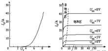
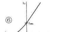
由于这种结构在VGS=0时,ID=0,称这种MOSFET为增强型。另一类MOSFET,在VGS=0时也有一定的ID(称为IDSS),这种MOSFET称为耗尽型。它的结构如图4所示,它的转移特性如图5所示。VP为夹断电压(ID=0)。
耗尽型与增强型主要区别是在制造SiO2绝缘层中有大量的正离子,使在P型衬底的界面上感应出较多的负电荷,即在两个N型区中间的P型硅内形成一N型硅薄层而形成一导电沟道,所以在VGS=0时,有VDS作用时也有一定的ID(IDSS);当VGS有电压时(可以是正电压或负电压),改变感应的负电荷数量,从而改变ID的大小。VP为ID=0时的-VGS,称为夹断电压。
责任编辑:Davia
【免责声明】
1、本文内容、数据、图表等来源于网络引用或其他公开资料,版权归属原作者、原发表出处。若版权所有方对本文的引用持有异议,请联系拍明芯城(marketing@iczoom.com),本方将及时处理。
2、本文的引用仅供读者交流学习使用,不涉及商业目的。
3、本文内容仅代表作者观点,拍明芯城不对内容的准确性、可靠性或完整性提供明示或暗示的保证。读者阅读本文后做出的决定或行为,是基于自主意愿和独立判断做出的,请读者明确相关结果。
4、如需转载本方拥有版权的文章,请联系拍明芯城(marketing@iczoom.com)注明“转载原因”。未经允许私自转载拍明芯城将保留追究其法律责任的权利。
拍明芯城拥有对此声明的最终解释权。


 产品分类
产品分类


 2012- 2022 拍明芯城ICZOOM.com 版权所有 客服热线:400-693-8369 (9:00-18:00)


