


 产品分类
产品分类
TI AMIC110无DDR EtherCAT Slave参考设计TIDEP-0105
 4150
4150
 拍明
拍明
原标题:TI AMIC110无DDR EtherCAT Slave参考设计TIDEP-0105
TI公司的AMIC110是基于ARM Cortex-A8处理器的多协议可编程通信处理器,为大多数以太网和主/从现场通信提供了容易使用的解决方案. 支持高级操作系统(HLOS).工作频率高达300MHz的Sitara™ ARM® Cortex®-A8 32位RISC处理器,并具有NEON SIMD协处理器,32KB L1指令和32KB 数据缓存,256KB L2缓存,176KB 引导ROM,62KB专用RAM,主要用在工业通信,连接工业驱动和背板I/O.本文介绍了AMIC110主要特性,功能框图以及无DDR EtherCAT® Slave AMIC110参考设计TIDEP-0105主要特性,框图,电路图,材料清单和PCB设计图.
The AMIC110 device is a multiprotocol programmable industrial communications processor providingready-to-use solutions for most industrial Ethernet and fieldbus communications slaves, as well as somemasters. The device is based on the ARM Cortex-A8 processor, peripherals, and industrial interfaceoptions. The device supports high-level operating systems (HLOS).Linux® and TI-RTOS are available freeof charge from TI. Other RTOS are also offered by TI ecosystem partners. The AMIC110 microprocessoris an ideal companion communications chip to the C2000 family of microcontrollers for connected drives.
The AMIC110 microprocessor contains the subsystems shown in Figure 1 and a brief description ofeach follows:
The microprocessor unit (MPU) subsystem is based on the ARM Cortex-A8 processor. The PRU-ICSS isseparate from the ARM core, allowing independent operation and clocking for greater efficiency andflexibility. The PRU-ICSS enables additional peripheral interfaces and real-time protocols such asEtherCAT, PROFINET IRT, EtherNet/IP, PROFIBUS, Ethernet Powerlink, Sercos III, and others.
Additionally, the programmable nature of the PRU-ICSS, along with its access to pins, events and allsystem-on-chip (SoC) resources, provides flexibility in implementing fast, real-time responses, specializeddata handling operations, custom peripheral interfaces, and in offloading tasks from the other processorcores of SoC.
AMIC110主要特性:
• Up to 300-MHz Sitara™ ARM® Cortex®-A8 32‑BitRISC Processor
– NEON™ SIMD Coprocessor
– 32KB of L1 Instruction and 32KB of Data CacheWith Single-Error Detection (Parity)
– 256KB of L2 Cache With Error Correcting Code(ECC)
– 176KB of On-Chip Boot ROM
– 64KB of Dedicated RAM
– Emulation and Debug - JTAG
– Interrupt Controller (up to 128 InterruptRequests)
• On-Chip Memory (Shared L3 RAM)
– 64KB of General-Purpose On-Chip MemoryController (OCMC) RAM
– Accessible to All Masters
– Supports Retention for Fast Wakeup
• External Memory Interfaces (EMIF)
– mDDR(LPDDR), DDR2, DDR3, DDR3LController:
– mDDR: 200-MHz Clock (400-MHz Data Rate)
– DDR2: 266-MHz Clock (532-MHz Data Rate)
– DDR3: 400-MHz Clock (800-MHz Data Rate)
– DDR3L: 400-MHz Clock (800-MHz DataRate)
– 16-Bit Data Bus
– 1GB of Total Addressable Space
– Supports One x16 or Two x8 Memory DeviceConfigurations
– General-Purpose Memory Controller (GPMC)
– Flexible 8-Bit and 16-Bit AsynchronousMemory Interface With up to Seven ChipSelects (NAND, NOR, Muxed-NOR, SRAM)
– Uses BCH Code to Support 4-, 8-, or 16-BitECC
– Uses Hamming Code to Support 1-Bit ECC
– Error Locator Module (ELM)
– Used in Conjunction With the GPMC toLocate Addresses of Data Errors from
Syndrome Polynomials Generated Using aBCH Algorithm
– Supports 4-, 8-, and 16-Bit per 512-ByteBlock Error Location Based on BCHAlgorithms
• Programmable Real-Time Unit Subsystem andIndustrial Communication Subsystem (PRU-ICSS)
– Supports Protocols such as EtherCAT®,PROFIBUS, PROFINET, EtherNet/IP™, and
More
– Two Programmable Real-Time Units (PRUs)
– 32-Bit Load/Store RISC Processor Capableof Running at 200 MHz
– 8KB of Instruction RAM With Single-ErrorDetection (Parity)
– 8KB of Data RAM With Single-Error Detection(Parity)
– Single-Cycle 32-Bit Multiplier With 64-BitAccumulator
– Enhanced GPIO Module Provides Shift-In/Out Support and Parallel Latch on External Signal
– 12KB of Shared RAM With Single-ErrorDetection (Parity)
– Three 120-Byte Register Banks Accessible byEach PRU
– Interrupt Controller (INTC) for Handling SystemInput Events
– Local Interconnect Bus for Connecting Internaland External Masters to the Resources Insidethe PRU-ICSS
– Peripherals Inside the PRU-ICSS:
– One UART Port With Flow Control Pins,Supports up to 12 Mbps
– One Enhanced Capture (eCAP) Module
– Two MII Ethernet Ports that Support IndustrialEthernet, such as EtherCAT
– One MDIO Port
• Power, Reset, and Clock Management (PRCM)Module
– Controls the Entry and Exit of Stand-By andDeep-Sleep Modes
– Responsible for Sleep Sequencing, PowerDomain Switch-Off Sequencing, Wake-Up Sequencing, and Power Domain Switch-OnSequencing
– Clocks
– Integrated 15- to 35-MHz High-frequencyOscillator Used to Generate a ReferenceClock for Various System and PeripheralClocks
– Supports Individual Clock Enable and DisableControl for Subsystems and Peripherals to
Facilitate Reduced Power Consumption
– Five ADPLLs to Generate System Clocks(MPU Subsystem, DDR Interface, USB and Peripherals [MMC and SD, UART, SPI, I2C],L3, L4, Ethernet, GFX [SGX530], LCD Pixel Clock (1))
– Power
– Two Nonswitchable Power Domains (Real-Time Clock [RTC], Wake-Up Logic[WAKEUP])
– Three Switchable Power Domains (MPUSubsystem [MPU], SGX530 [GFX](1),Peripherals and Infrastructure [PER])
– Implements SmartReflex™ Class 2B for CoreVoltage scaling Based On Die Temperature,Process Variation, and Performance(Adaptive Voltage Scaling [AVS])
– Dynamic Voltage Frequency Scaling (DVFS)
• Real-Time Clock (RTC)
– Real-Time Date (Day-Month-Year-Day of Week)and Time (Hours-Minutes-Seconds) Information
– Internal 32.768-kHz Oscillator, RTC Logic and1.1-V Internal LDO
– Independent Power-on-Reset(RTC_PWRONRSTn) Input
– Dedicated Input Pin (EXT_WAKEUP) forExternal Wake Events
– Programmable Alarm Can be Used to GenerateInternal Interrupts to the PRCM (for Wakeup) orCortex-A8 (for Event Notification)
– Programmable Alarm Can be Used WithExternal Output (PMIC_POWER_EN) to Enablethe Power Management IC to Restore Non-RTCPower Domains
• Peripherals
– Up to Two USB 2.0 High-Speed OTG PortsWith Integrated PHY
– Up to Two Controller-Area Network (CAN) Ports
– Supports CAN Version 2 Parts A and B
– Up to Two Multichannel Audio Serial Ports(McASPs)
– Transmit and Receive Clocks up to 50 MHz
– Up to Four Serial Data Pins per McASP PortWith Independent TX and RX Clocks
– Supports Time Division Multiplexing (TDM),Inter-IC Sound (I2S), and Similar Formats
– Supports Digital Audio Interface Transmission(SPDIF, IEC60958-1, and AES-3 Formats)
– FIFO Buffers for Transmit and Receive (256Bytes)
– Up to Six UARTs
– All UARTs Support IrDA and CIR Modes
– All UARTs Support RTS and CTS FlowControl
– UART1 Supports Full Modem Control
– Up to Two Master and Slave McSPI SerialInterfaces
– Up to Two Chip Selects
– Up to 48 MHz
– Up to Three MMC, SD, SDIO Ports
– 1-, 4- and 8-Bit MMC, SD, SDIO Modes
– MMCSD0 has Dedicated Power Rail for 1.8‑Vor 3.3-V Operation
– Up to 48-MHz Data Transfer Rate
– Supports Card Detect and Write Protect
– Complies With MMC4.3, SD, SDIO 2.0Specifications
– Up to Three I2C Master and Slave Interfaces
– Standard Mode (up to 100 kHz)
– Fast Mode (up to 400 kHz)
– Up to Four Banks of General-Purpose I/O(GPIO) Pins
– 32 GPIO Pins per Bank (Multiplexed WithOther Functional Pins)
– GPIO Pins Can be Used as Interrupt Inputs(up to Two Interrupt Inputs per Bank)
– Up to Three External DMA Event Inputs that canAlso be Used as Interrupt Inputs
– Eight 32-Bit General-Purpose Timers
– DMTIMER1 is a 1-ms Timer Used forOperating System (OS) Ticks
– DMTIMER4–DMTIMER7 are Pinned Out
– One Watchdog Timer
– 12-Bit Successive Approximation Register(SAR) ADC
– 200K Samples per Second
– Input can be Selected from any of the EightAnalog Inputs Multiplexed Through an 8:1
Analog Switch
– Up to Three Enhanced High-Resolution PWMModules (eHRPWMs)
– Dedicated 16-Bit Time-Base Counter WithTime and Frequency Controls
– Configurable as Six Single-Ended, Six Dual-Edge Symmetric, or Three Dual-Edge Asymmetric Outputs
• Device Identification
– Contains Electrical Fuse Farm (FuseFarm) ofWhich Some Bits are Factory Programmable
– Production ID
– Device Part Number (Unique JTAG ID)
– Device Revision (Readable by Host ARM)
• Debug Interface Support
– JTAG and cJTAG for ARM (Cortex-A8 andPRCM), PRU-ICSS Debug
– Supports Device Boundary Scan
– Supports IEEE 1500
• DMA
– On-Chip Enhanced DMA Controller (EDMA) hasThree Third-Party Transfer Controllers (TPTCs)and One Third-Party Channel Controller(TPCC), Which Supports up to 64
Programmable Logical Channels and EightQDMA Channels. EDMA is Used for:
– Transfers to and from On-Chip Memories
– Transfers to and from External Storage(EMIF, GPMC, Slave Peripherals)
• Inter-Processor Communication (IPC)
– Integrates Hardware-Based Mailbox for IPC andSpinlock for Process Synchronization BetweenCortex-A8, PRCM, and PRU-ICSS
– Mailbox Registers that Generate Interrupts
– Four Initiators (Cortex-A8, PRCM, PRU0,PRU1)
– Spinlock has 128 Software-Assigned LockRegisters
• Security
– Secure Boot
• Boot Modes
– Boot Mode is Selected Through BootConfiguration Pins Latched on the Rising Edge of the PWRONRSTn Reset Input Pin
• Package:
– 324-Pin S-PBGA-N324 Package(ZCZ Suffix), 0.80-mm Ball Pitch
AMIC110应用:
• Industrial Communications
• Connected Industrial Drives
• Backplane I/O

图1.AMIC110 MCU功能框图
无DDR EtherCAT® Slave AMIC110参考设计TIDEP-0105
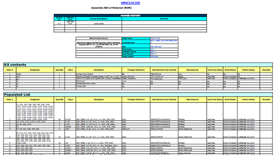
EtherCAT® (Ethernet for Control AutomationTechnology) continuously grows to establish itself as adominant, industrial, Ethernet network. The DDR-lessEtherCAT reference design serves as a referencedesign for a completely new and low-cost, DDR-less,EtherCAT slave implementation on the AMIC110, amultiprotocol industrial communications system on achip (SoC). This reference design showcases theability to run a full EtherCAT slave stack entirely on theinternal memory of the SoC. Significant system bill ofmaterials (BOM) and board savings are achieved withthis reference design by eliminating an external ASICand DDR. Additionally, applications such as connectedindustrial drives and communications modules cansignificantly benefit from the faster speeds that areachieved by eliminating external memory transfers forEtherCAT.
EtherCAT, invented by Beckhoff Automation in Germany and later standardized by the ETG, is a realtime,industrial, Ethernet standard for industrial automation applications, such as input/output (I/O)devices, communication modules, sensors, and programmable logic controllers (PLCs).
Traditional Ethernet has seen unparalleled adoption in diverse applications, but in industrial environmentsit is still not efficient enough for small amounts of data exchange, due to its lower determinism for real-timeoperation and also works in which the network nodes must be connected through switches. EtherCATimproves upon traditional Ethernet by implementing on-the-fly processing, where the nodes in theEtherCAT network read the data from a frame as it passes through. All EtherCAT frames originate fromthe EtherCAT master, which sends commands and data to the slaves. Any data to be sent back to themaster is written by the slave onto the frame as it passes through.
Many simple EtherCAT devices such as digital I/Os can be created using single FPGA or ASIC solutionsavailable today. In EtherCAT nodes where additional processing power is needed, an external processor,often with on-chip Flash memory, is connected to the EtherCAT ASIC/FPGA for handling application-levelprocessing. The cost of such architecture is higher than that of simple digital I/O devices, but it comes withflexibility in that developers can select a processor that suits their needs. In yet another approach, theEtherCAT implementation is one of the peripherals in the device that has an integrated CPU. Many FPGAdevices can configure a processor in the FPGA or already have an integrated processor. The FPGAs are flexible, but depending on the CPU selection there is a risk that costs or operating frequency targets willbe challenging to meet.
To meet the demand of cost-sensitive, industrial automation applications, this TI Design presents areference design for a completely new, compact implementation that provides a low-cost, DDR-less,EtherCAT Slave with the AMIC110, a multiprotocol programmable industrial communications SoC.
Significant system BOM and board savings are achieved with the solution by eliminating an external ASICand DDR. In addition, the software- and firmware-based architecture and the PRU-ICSS IndustrialCommunications suite can scale to support multiple industrial Ethernet and fieldbus communicationstandards.
参考设计TIDEP-0105主要特性:
• Passes EtherCAT Slave Conformance Testing Tool(CTT) From EtherCAT Technology Group (ETG)
• Entire EtherCAT Slave Stack Hosted On InternalMemory
• Eight Fieldbus Memory Management Units(FMMUs) and Sync Managers (SMs) Supported ByPRU-ICSS Firmware
• SYNC0/SYNC1 Generation With Distribute Clock(DC)
• Enhanced Link-Loss Detection For Loop Control
• Helps Improve System Performance With RemovalOf Latencies Associated With External MemoryAccesses
• Optionally Connect With C2000™ MCU,TMS320F28379D, To Provide Low-Cost, High-Performance, Industrial Drive Solutions
参考设计TIDEP-0105应用:
• Industrial Robot Communication Module
• CPU (Programmable Logic Controller)
• Communication Module
• AC Drive Wired and Wireless Communication
• Servo Drive Wired and Wireless Communication
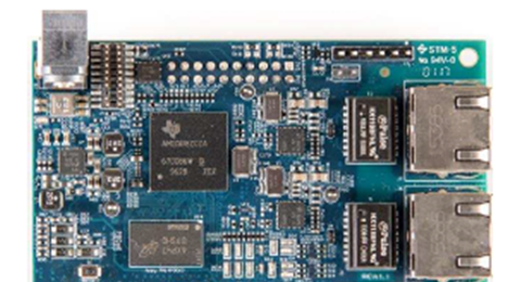
图2.参考设计TIDEP-0105外形图

图3.参考设计TIDEP-0105框图
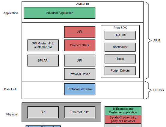
图4.参考设计TIDEP-0105软件架构框图
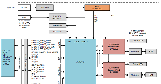
图5.AMIC110工业通信引擎框图

图6.AMIC110 ICE硬件建立图
AMIC110 ICE Schematic Files
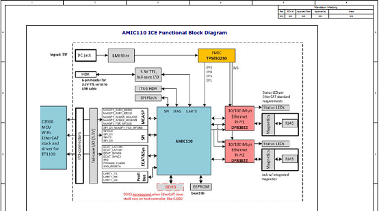
图7.AMIC110 ICE电路图(1)
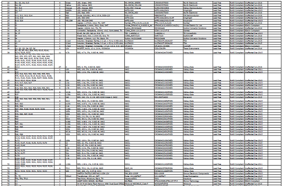
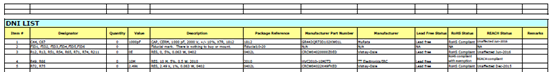
AMIC110 ICE材料清单:
责任编辑:HanFeng
【免责声明】
1、本文内容、数据、图表等来源于网络引用或其他公开资料,版权归属原作者、原发表出处。若版权所有方对本文的引用持有异议,请联系拍明芯城(marketing@iczoom.com),本方将及时处理。
2、本文的引用仅供读者交流学习使用,不涉及商业目的。
3、本文内容仅代表作者观点,拍明芯城不对内容的准确性、可靠性或完整性提供明示或暗示的保证。读者阅读本文后做出的决定或行为,是基于自主意愿和独立判断做出的,请读者明确相关结果。
4、如需转载本方拥有版权的文章,请联系拍明芯城(marketing@iczoom.com)注明“转载原因”。未经允许私自转载拍明芯城将保留追究其法律责任的权利。
拍明芯城拥有对此声明的最终解释权。
相关资讯
:
基于MC33771主控芯片的新能源锂电池管理系统解决方案

AMIC110 32位Sitara ARM MCU开发方案

基于AMIC110多协议可编程工业通信处理器的32位Sitara ARM MCU开发方案

基于展讯SC9820超低成本LTE芯片平台的儿童智能手表解决方案

基于TI公司的AM437x双照相机参考设计

基于MTK6580芯片的W2智能手表解决方案


 2012- 2022 拍明芯城ICZOOM.com 版权所有 客服热线:400-693-8369 (9:00-18:00)


